|
2
|
|
3
|
|
4
|
|
6
|
|
7
|
|
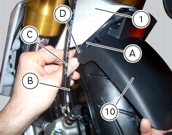
10
|
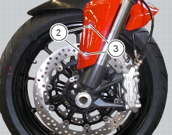
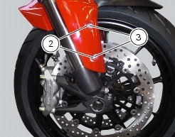
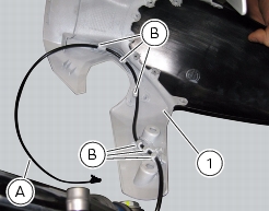
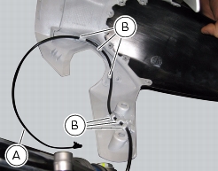
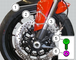
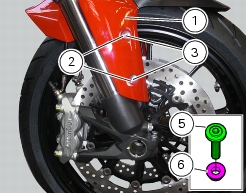
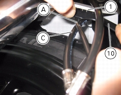
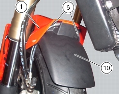
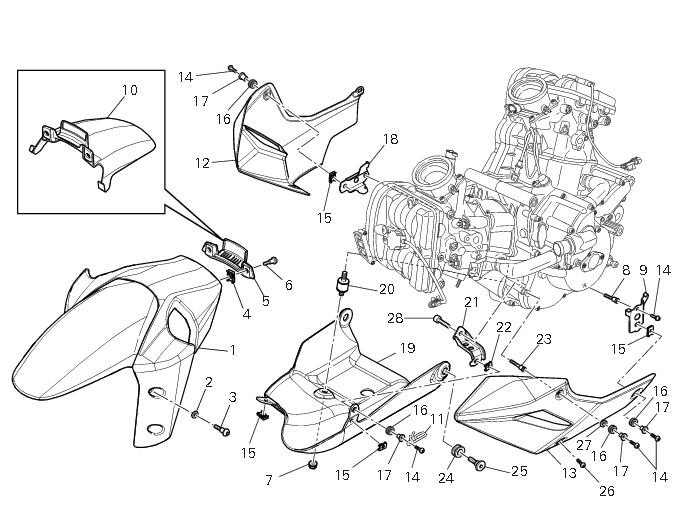
Front mudguard – front section
|
|
11
|
|
12
|
|
13
|
|
14
|
|
15
|
|
17
|
|
22
|
|
25
|
|
26
|
|
27
|
|
28
|