9 -
High beam lights not working
Fault codes
DDS: Light relay diagnosis -> High beam (generic high beam relay malfunction indication)
Dashboard: the error “High beam” is shown on the service display. The EOBD warning light activates.
Wiring diagram
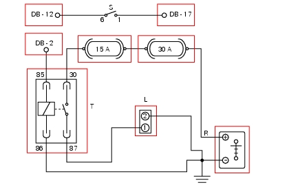
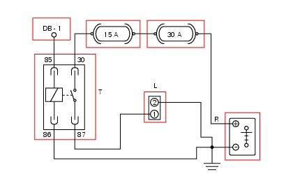
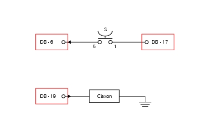
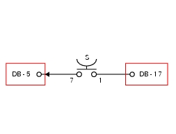
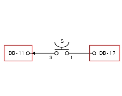
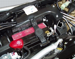
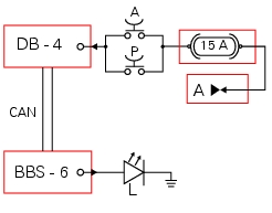
DB Dashboard connection, L high beam lights connection, T high beam relay, S high beam light switch, R positive battery termi­nal. 6 blue – B, 1 red/blue – R/B, 85 yellow/grey – Y/Gr, 30 orange – O, 86 black – Bk, 87 yellow/black – Y/Bk, 2 black – Bk.
Location of connections and components
A
B
C
D
A
B
C
D
E
Location of left hand handlebar switchgear set connection.
PIN numbering for wiring harness side dashboard connector.
Checks
Check integrity of incandescent high beam headlamp bulbs. If necessary, power the bulbs with a 12 V external power supply to test function (connect correctly as indicated in the wiring diagram).
Check integrity of the 15A fuse (light fuse) and of the 30A fuse (main fuse).
Check congruence of ground connection on high beam headlamp
Test function of high beam relay, powering its electric winding (internal coil) with 12V. In this state, PIN 30 and PIN 87 should close (continuity between PINs). With no power, the PINs must be open (no continuity between PINs).
Check that when the high beam switch is turned to the high beams on position, there is continuity across its two electric termi­nals (PIN 6 and PIN 1).
Check that there is a voltage of 5 V on PIN 1 of the high beam switch arriving from dashboard PIN 17.
Check that with the high beam switch turned on, there is a voltage of 12 V on PIN 85 of the relay arriving from dashboard PIN 2
Check the integrity of the electrical circuit and connections (short circuits to ground, short circuits to Vdc, open circuits).
If none of the aforementioned tests identifies the problem, replace the instrument panel.
 
Note
Check integrity of electric circuit – short-circuit to Vdc = with instrument panel on, using a voltmeter, a voltage is measured be­tween the wire tested and ground.
Check integrity of electric circuit – short-circuit to ground = with the battery cables disconnected, using an ohmmeter, continuity is detected between the wire tested and ground.
Check integrity of electric circuit – open circuit = with the battery cables disconnected, using an ohmmeter, no continuity is de­tected between the two ends of the wire tested.
Low beam lights not working
Fault codes
DDS: Light relay diagnosis -> Low beam (generic low beam relay malfunction indication).
Dashboard: the error “Low beam” is shown on the service display. The EOBD warning light activates.
Wiring diagram
DB Dashboard connection, T low beam relay, L low beam connection, R positive battery terminal. 85 yellow/white – Y/W, 30 orange – O, 86 black – Bk, 87 white – W, 2 black – Bk.
Location of connections and components
A
B
C
D
A
B
C
D
E
PIN numbering for wiring harness side dashboard connector.
Checks
Check integrity of incandescent low beam headlamp bulbs. If necessary, power the bulbs with a 12 V external power supply to test function (connect correctly as indicated in the wiring diagram).
Check integrity of the 15A fuse (light fuse) and of the 30A fuse (main fuse).
Check congruence of ground connection on low beam headlamp.
Test function of low beam relay, powering its electric winding (internal coil) with 12V. In this state, PIN 30 and PIN 87 should close (continuity between PINs). With no power, the PINs must be open (no continuity between PINs).
Check that there is a voltage of 12 V on PIN 85 of the relay arriving from dashboard PIN 1.
Check the integrity of the electrical circuit and connections (short-circuits to ground, short-circuits to Vdc, open circuits).
If none of the aforementioned tests identifies the problem, replace the instrument panel.
Note
Check integrity of electric circuit – short-circuit to Vdc = with instrument panel on, using a voltmeter, a voltage is measured be­tween the wire tested and ground.
Check integrity of electric circuit – short-circuit to ground = with the battery cables disconnected, using an ohmmeter, continuity is detected between the wire tested and ground.
Check integrity of electric circuit – open circuit = with the battery cables disconnected, using an ohmmeter, no continuity is de­tected between the two ends of the wire tested.
 
Horn not working
Fault codes
DDS: Horn diagnosis -> Short circuit to ground (S.C. GND)
Dashboard: the error “Claxon” (horn) is shown on the service display. The EOBD warning light activates.
Wiring diagram
DB Dashboard connection, S horn button. 5 blue/white – B/W, 1 red/blue – R/B, DB 19 purple/black – V/Bk.
Location of connections and components
Location of left hand handlebar switchgear set connection.
Location of horn with relative connection.
PIN numbering for wiring harness side dashboard connector.
Checks
If the indicated fault code has been generated by the DDS, check that the electric connection between the dashboard and the horn is not short circuited to ground.
Test horn function by powering with an external 12V power supply.
Check congruence of the ground connection on the horn.
Test horn button function. When the button is pressed, there must be continuity between its two electric terminals (PIN 5 and PIN 1).
Check that there is a voltage of 5V on PIN 1 of the horn button arriving from dashboard PIN 17.
Check that the horn receives a voltage of 12 V arriving from dashboard PIN 19 when the horn button is pressed.
Check the integrity of the electrical circuit and connections (short-circuits to ground, short-circuits to Vdc, open circuits).
If none of the aforementioned tests identifies the problem, replace the instrument panel.
Note
Check integrity of electric circuit – short-circuit to Vdc = with instrument panel on, using a voltmeter, a voltage is measured be­tween the wire tested and ground.
Check integrity of electric circuit – short-circuit to ground = with the battery cables disconnected, using an ohmmeter, continuity is detected between the wire tested and ground.
Check integrity of electric circuit – open circuit = with the battery cables disconnected, using an ohmmeter, no continuity is de­tected between the two ends of the wire tested.
 
Turn indicators not working
Fault codes
DDS: no fault code displayed.
Dashboard: no fault code displayed.
Wiring diagram
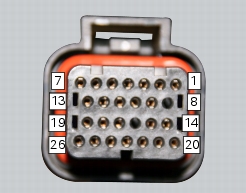
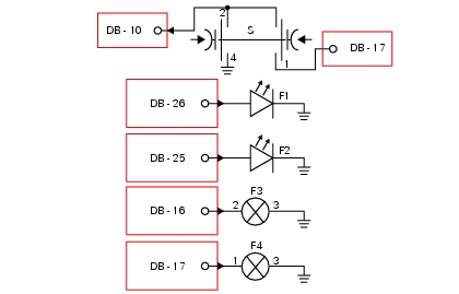
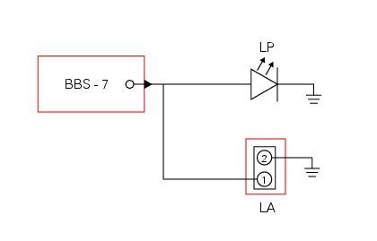
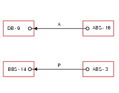
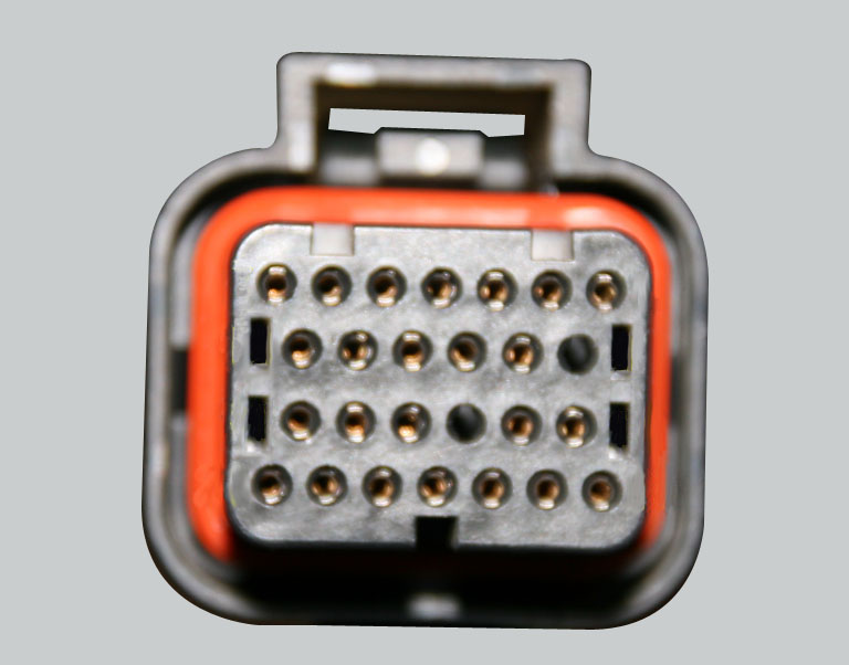
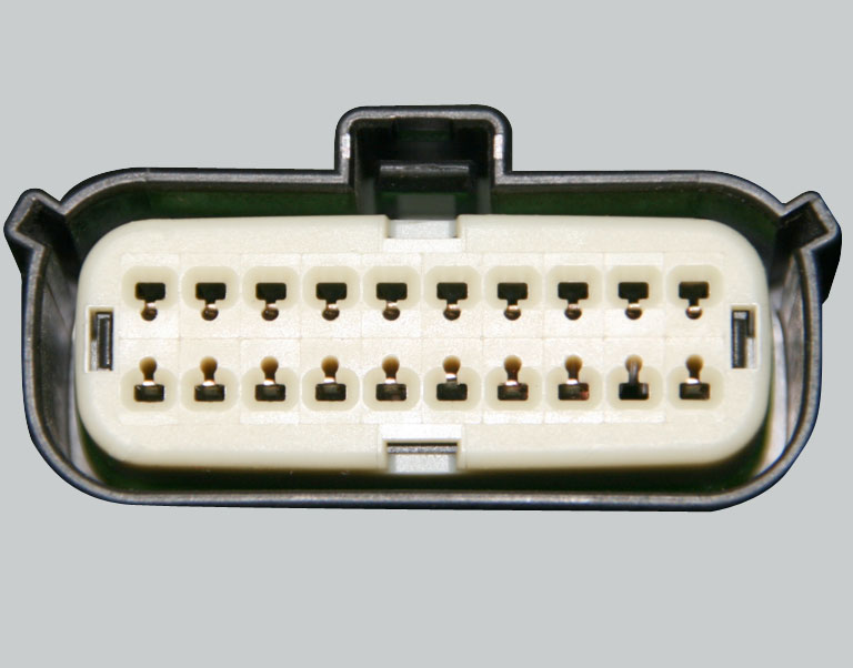
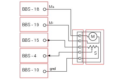
DB Dashboard connection, BBS unit connection, S turn indicator button, F1 front left turn indicator, F2 front right turn indicator, F3 rear left turn indicator, F4 rear right turn indicator. 2 on grey button – Gr, 1 on red/blue button – R/B, 4 on black button – Bk, DB 26 white/black W/Bk, DB 25 green/black – G/Bk, BBS 16 white/green – W/G, BBS 17 white/black W/Bk.
Location of connections and components
Location of rear turn indicator and license plate light connection.
Location of left hand handlebar switchgear set connection.
Location of front right turn indicator connection.
Location of front left turn indicator connection.
PIN numbering for wiring harness side dashboard connector.
PIN numbering of wiring harness side BBS unit connection.
Checks
Check integrity of incandescent bulbs in rear turn indicators. If necessary, power the bulbs with a 12 V external power supply to test function (connect correctly as indicated in the wiring diagram). The front turn indicators use LED light units, which are pow­ered with square wave PWM power and CANNOT be tested with an external power supply.
Check congruence of the ground connection on the turn indicators.
Test turn indicator button function. Pushing the button in one direction closes the circuit between dashboard PIN 17 and PIN 10 (button PIN 2 and PIN 1), pushing in the opposite direction connects dashboard PIN 10 to ground (button PIN 2)
Check congruence of the ground connection on turn indicator button PIN 4.
Check that there is a voltage of 5 V on PIN 1 of the turn indicator button arriving from dashboard PIN 17.
Check the integrity of the electrical circuit and connections (short-circuits to ground, short-circuits to Vdc, open circuits).
If none of the aforementioned tests identify the problem, but the turn indicator button does not receive power correctly from dashboard PIN 17, replace the dashboard.
If none of the aforementioned tests identifies the problem and either one or both of the front turn indicators are not working, replace the malfunctioning turn indicator. If the fault persists after replacement, replace the dashboard.
If none of the aforementioned tests identifies the problem and either one or both of the rear turn indicators are not working, re­place the BBS unit.
Note
Check integrity of electric circuit – short-circuit to Vdc = with instrument panel on, using a voltmeter, a voltage is measured be­tween the wire tested and ground.
Check integrity of electric circuit – short-circuit to ground = with the battery cables disconnected, using an ohmmeter, continuity is detected between the wire tested and ground.
Check integrity of electric circuit – open circuit = with the battery cables disconnected, using an ohmmeter, no continuity is de­tected between the two ends of the wire tested.
High beam flash not working - start/stop lap function not working
Fault codes
DDS: no fault code displayed.
Dashboard: no fault code displayed.
Wiring diagram
DB Dashboard connection, S high beam flash button. 7 orange – O, 1 red/blue – R/B.
Location of connections and components
Location of left hand handlebar switchgear set connection.
PIN numbering for wiring harness side dashboard connector.
Checks
Test high beam flash button function. When the button is pressed, there must be continuity between its two electric terminals (PIN 1 and PIN 7).
Check that there is a voltage of 5V on PIN 1 of the high beam flash button arriving from dashboard PIN 17.
Check the correct operation of the high beam headlamps (see paragraph “High beam lights not working”) of this Section.
Check the integrity of the electrical circuit and connections (short circuits to ground, short circuits to Vdc, open circuits).
If none of the aforementioned tests identifies the problem, replace the dashboard.
 
 
Note
Check integrity of electric circuit – short-circuit to Vdc = with instrument panel on, using a voltmeter, a voltage is measured be­tween the wire tested and ground
Check integrity of electric circuit – short-circuit to ground = with the battery cables disconnected, using an ohmmeter, continuity is detected between the wire tested and ground
Check integrity of electric circuit – open circuit = with the battery cables disconnected, using an ohmmeter, no continuity is de­tected between the two ends of the wire tested)
License plate light not working
Fault codes
DDS: no fault code displayed.
Dashboard: no fault code displayed.
Wiring diagram
DB Dashboard connection, L license plate light. DB 18 yellow – Y, 3 black – Bk.
Location of connections and components
Location of rear turn indicator and license plate light connection.
PIN numbering for wiring harness side dashboard connector.
Checks
The license plate light receives square wave PWM power from the dashboard. Check the integrity of the incandescent bulb in the number plate light. If necessary, power the number plate light with a 12 V external power supply to test function (connect correctly as indicated in the wiring diagram).
Check congruence of the ground connection on the number plate light.
Check the integrity of the electrical circuit and connections (short-circuits to ground, short-circuits to Vdc, open circuits).
If none of the aforementioned tests identifies the problem, replace the instrument panel.
Note
Check integrity of electric circuit – short-circuit to Vdc = with instrument panel on, using a voltmeter, a voltage is measured be­tween the wire tested and ground.
Check integrity of electric circuit – short-circuit to ground = with the battery cables disconnected, using an ohmmeter, continuity is detected between the wire tested and ground.
Check integrity of electric circuit – open circuit = with the battery cables disconnected, using an ohmmeter, no continuity is de­tected between the two ends of the wire tested.
Running lights not working
Fault codes
DDS: no fault code displayed.
Dashboard: no fault code displayed.
Wiring diagram
BBS BBS unit connection, LA front running light, LP rear running light. BBS 7 yellow – Y, 2 black – Bk, rear running light-stop light ground, black – Bk.
Location of connections and components
A
B
C
D
E
Rear running light and stop light connection.
PIN numbering of wiring harness side BBS unit connection.
Checks
The front and rear parking lights use LED light units and receive a 12 V power supply. Power the parking lights with an external 12 V power supply to test function (connect correctly as indicated in the wiring diagram).
Check congruence of the ground connection on the running lights.
Check that the parking lights receive 12V arriving from PIN 7 of the BBS.
Check the integrity of the electrical circuit and connections (short-circuits to ground, short-circuits to Vdc, open circuits).
If none of the aforementioned tests identifies the problem, replace the BBS.
Note
Check integrity of electric circuit – short-circuit to Vdc = with instrument panel on, using a voltmeter, a voltage is measured be­tween the wire tested and ground.
Check integrity of electric circuit – short-circuit to ground = with the battery cables disconnected, using an ohmmeter, continuity is detected between the wire tested and ground.
Check integrity of electric circuit – open circuit = with the battery cables disconnected, using an ohmmeter, no continuity is de­tected between the two ends of the wire tested.
 
Dashboard menu option scrolling not possible
Fault codes
DDS: no fault code displayed
Dashboard: no fault code displayed
Wiring diagram
DB Dashboard connection. The buttons on the left hand handlebar perform the functions Set Up and Set Down in the dashboard menu. 8 blue/yellow – B/Y, 4 black – Bk, 1 red/blue – R/ B.
Location of connections and components
Location of left hand handlebar switchgear set connection.
PIN numbering for wiring harness side dashboard connector.
Checks
Test menu scroll button function. Pushing the button in one direction closes the circuit between dashboard PIN 17 and PIN 3 (button PIN 8 and PIN 1), pushing in the opposite direction connects dashboard PIN 3 to ground (button PIN 8 closed on button PIN 4 linked to the ground).
Check congruence of the ground connection on menu scroll button PIN 4.
Check that there is a voltage of 5 V on PIN 1 of the menu scroll button arriving from dashboard PIN 17.
Check the integrity of the electrical circuit and connections (short-circuits to ground, short-circuits to Vdc, open circuits).
If none of the aforementioned tests identifies the problem, replace the instrument panel.
Note
Check integrity of electric circuit – short-circuit to Vdc = with instrument panel on, using a voltmeter, a voltage is measured be­tween the wire tested and ground.
Check integrity of electric circuit – short-circuit to ground = with the battery cables disconnected, using an ohmmeter, continuity is detected between the wire tested and ground.
Check integrity of electric circuit – open circuit = with the battery cables disconnected, using an ohmmeter, no continuity is de­tected between the two ends of the wire tested.
Resetting turn indicators not possible - accessing dashboard menu not possible
Fault codes
DDS: no fault code displayed
Dashboard: no fault code displayed
Wiring diagram
DB Dashboard connection, S turn indicator reset-dashboard menu access button. 3 brown – Br, 1 red/blue – R/B.
Location of connections and components
Location of left hand handlebar switchgear set connection.
PIN numbering for wiring harness side dashboard connector.
Checks
Test turn indicator reset button function. When the button is pressed, there must be continuity between its two electric terminals (PIN 3 and PIN 1).
Check that there is a voltage of 5V on PIN 1 of the turn indicator reset button arriving from dashboard PIN 17.
Check the integrity of the electrical circuit and connections (short-circuits to ground, short-circuits to Vdc, open circuits).
If none of the aforementioned tests identifies the problem, replace the instrument panel.
Note
Check integrity of electric circuit – short-circuit to Vdc = with instrument panel on, using a voltmeter, a voltage is measured be­tween the wire tested and ground.
Check integrity of electric circuit – short-circuit to ground = with the battery cables disconnected, using an ohmmeter, continuity is detected between the wire tested and ground.
Check integrity of electric circuit – open circuit = with the battery cables disconnected, using an ohmmeter, no continuity is de­tected between the two ends of the wire tested.
Fuel level not displayed correctly
Fault codes
DDS: Fuel sensor diagnosis -> Short circuit to Vdc or open circuit (S.C. Vdc or C.O.) – Short circuit to ground (S.C. GND) – Con­gruence (Generic error – signal not correct).
Dashboard: the error “Fuel sensor” is shown on the service display. The EOBD warning light activates.
Fault indication
If the dashboard receives the “Fuel Sensor” error information via the CAN line:
-
-
-
If the dashboard does not receive fuel level information via the CAN line:
-
-
-
Wiring diagram
BBS BBS unit connection, S fuel level sensor. 1 blue/black – B/Bk, 2 white/blue – W/B.
Location of connections and components
Location of fuel level sensor with cable and connection.
PIN numbering of wiring harness side BBS unit connection.
Checks
Test fuel level sensor function. The sensor resistance when the tank is completely empty must be 150 Ohm, whereas the sensor resistance with a completely full tank must be 22770 Ohm. Measure the resistance between PIN 1 and PIN 2 of the sensor, with the connection disconnected.
Check the integrity of the electrical circuit and connections (short-circuits to ground, short-circuits to Vdc, open circuits).
If none of the aforementioned tests identify the problem, replace the fuel level sensor. If the fault has not been resolved, replace the BBS unit.
Warning
the vehicle must be in KEY OFF state when refuelling. At the subsequent KEY ON, the system acquires the new fuel level.
 
Note
Check integrity of electric circuit – short-circuit to Vdc = with instrument panel on, using a voltmeter, a voltage is measured be­tween the wire tested and ground.
Check integrity of electric circuit – short-circuit to ground = with the battery cables disconnected, using an ohmmeter, continuity is detected between the wire tested and ground.
Check integrity of electric circuit – open circuit = with the battery cables disconnected, using an ohmmeter, no continuity is de­tected between the two ends of the wire tested.
Gear indicator display on dashboard shows dashes, engaged gear not displayed correctly, idle speed irregular with gearbox in neutral.
Fault codes
DDS: Gear sensor diagnosis -> Short circuit to ground or open circuit (S.C. GND or C.O.) – Short circuit to Vdc (S.C. Vdc) – Con­gruence (Generic error – signal not correct).
Dashboard: The error “Gear sensor” is shown on the service display. The EOBD warning light activates.
Fault indication
If the dashboard receives the “Gear” error information via the CAN line:
-
-
If the dashboard does not receive the gear or neutral engaged information via the CAN line:
-
-
If the dashboard receives incorrect gear engaged information via the CAN line with the engine running:
-
Warning
It is possible that the gear engaged or neutral engaged information is not being generated because the gear position self-acqui­sition procedure has not been performed (gear sensor not initialised).
Wiring diagram
BBS BBS unit connection, S gear position sensor. BBS 15 brown/red – Br/R (5V), BBS 13 yellow/green Y/G, BBS 10 black/blue – Bk/B.
Location of connections and components
Location of gear sensor connection.
PIN numbering of wiring harness side BBS unit connection.
Checks
The gear sensor is a Hall effect unit. Ground is on PIN 10 of the BBS unit, 5 V power is on PIN 15 of the BBS unit, PIN 13 of the BBS is the input for the signal generated by the sensor. Check that the sensor receives 5 V power.
Check the integrity of the electrical circuit and connections (short-circuits to ground, short-circuits to Vdc, open circuits).
Perform the gear self-acquisition procedure.
If none of the aforementioned tests identify the problem, replace the gear sensor then perform the gear self-acquisition proce­dure. If the fault has not been resolved, replace the BBS unit.
Warning
the system is capable of compensating for normal mechanical wear of the sensor probe. Certain faults may be due to excessive mechanical wear between the sensor and gear selector drum.
Warning
The engine control unit uses the neutral engaged signal generated by the gear sensor, together with the clutch lever pulled signal, to manage idle speed.
Note
Check integrity of electric circuit – short-circuit to Vdc = with instrument panel on, using a voltmeter, a voltage is measured be­tween the wire tested and ground.
Check integrity of electric circuit – short-circuit to ground = with the battery cables disconnected, using an ohmmeter, continuity is detected between the wire tested and ground.
Check integrity of electric circuit – open circuit = with the battery cables disconnected, using an ohmmeter, no continuity is de­tected between the two ends of the wire tested.
Gear self-acquisition procedure
The gear self-acquisition procedure must be launched from the DDS instrument. This ensures that the data stored previously is deleted and enables the BBS to run a new gear acquisition procedure. With the engine running and the motorcycle in motion:
-
Select first gear, pulling the clutch lever completely, dashes “- -“ appear in the gear indicator display. Release the clutch, the letter “C” appears in the display. Keep the motorcycle in this gear for at least five seconds. Select the next gear
-
-
-
-
-
-
 
Dashes shown instead of speed indication or indicated speed is incorrect
Fault codes
DDS: Speed sensor diagnosis -> Max. speed (Max. speed error – signal not correct) – Minimum speed (Min speed error – signal not correct) – Congruence (Correlation speed error – signal not correct).
Dashboard: the error “Speed sensor” is shown on the service display. The EOBD warning light activates.
Fault indication
If the dashboard does not receive “Vehicle speed” information via the CAN line:
-
-
If:
-
or
-
The error “Speed sensor” is shown on the dashboard service display.
Warning
The dashboard speed indicator also displays fixed dashes if vehicle speed exceeds 299 Km/h.
Warning
DTC is disabled in the event of a wheel speed sensor error.
Wiring diagram
BBS BBS unit connection, DB Dashboard connection, ABS ABS connection. BBS 14 green/purple – G/V, DB 9 blue – B.
Wiring harness side ABS connection.
PIN numbering for wiring harness side dashboard connector.
PIN numbering of wiring harness side BBS unit connection.
Checks
For diagnosing wheel speed sensors, consult the section relative to diagnosing the ABS unit.
Check the integrity of the electrical circuit and connections (short-circuits to ground, short-circuits to Vdc, open circuits).
If the above test did not identify the problem, contact Ducati.
Note
Check integrity of electric circuit – short-circuit to Vdc = with instrument panel on, using a voltmeter, a voltage is measured be­tween the wire tested and ground.
Check integrity of electric circuit – short-circuit to ground = with the battery cables disconnected, using an ohmmeter, continuity is detected between the wire tested and ground.
Check integrity of electric circuit – open circuit = with the battery cables disconnected, using an ohmmeter, no continuity is de­tected between the two ends of the wire tested.
Propagation of wheel speed signals and generation of vehicle speed signal
The diagram illustrates how the vehicle speed information is generated and how it is transmitted to the dashboard.
The front wheel speed sensor signal is replicated by the ABS unit and transmitted to the dashboard, whereas the rear wheel speed sensor signal is replicated by the ABS unit and transmitted to the BBS unit.
The replicated front wheel speed sensor signal (1 in diagram) is transmitted by the dashboard over the CAN line and acquired by the BBS unit. The BBS now has both the replicated front wheel speed sensor signal and the replicated rear wheel speed sensor signal.
Using the replicated rear wheel speed signal and the circumference of the wheel itself, the BBS unit calculates the vehicle speed (2 in diagram). This parameter is used by the Ducati Traction Control (DTC) function together with the front wheel speed and the circumference of the front wheel itself, in order to implement engine torque limiting strategies when required.
The vehicle speed calculated by the BBS is transmitted over the CAN line (3 in diagram) and acquired by the dashboard, which displays the speed information accordingly.
 
On motorcycles with no ABS unit, the front wheel speed sensor is connected directly to dashboard and the rear wheel speed sensor is connected directly to the BBS.
 
ABS fault indicator not working
Fault codes
DDS: displays a fault code described in the description of the ABS system.
Dashboard: no fault code displayed.
Wiring diagram
BBS unit connection BBS, ABS unit connection ABS. BBS 2 light blue – Lb.
Wiring harness side ABS connection.
PIN numbering of wiring harness side BBS unit connection.
Checks
The ABS fault indicator indicates the occurrence of one or more faults in the antilock brake system, or if the system itself has been disabled by the rider, using the relative control. The signal causing activation of the ABS fault indicator in the event of an antilock brake system malfunction, comes directly from the ABS control unit, and the information is transmitted over the CAN line by the BBS unit, so that it may be acquired by the dashboard, where the indicator itself is located.
Diagnose the ABS unit.
Check the integrity of the electrical circuit and connections (short-circuits to ground, short-circuits to Vdc, open circuits).
If the above test did not identify the problem, contact Ducati.
 
Note
Check integrity of electric circuit – short-circuit to Vdc = with instrument panel on, using a voltmeter, a voltage is measured be­tween the wire tested and ground
Check integrity of electric circuit – short-circuit to ground = with the battery cables disconnected, using an ohmmeter, continuity is detected between the wire tested and ground
Check integrity of electric circuit – open circuit = with the battery cables disconnected, using an ohmmeter, no continuity is de­tected between the two ends of the wire tested)
ABS disabled information not displayed.
Fault codes
DDS: displays a fault code described in the description of the ABS system.
Dashboard: no fault code displayed.
Wiring diagram
BBS unit connection BBS, ABS unit connection ABS. BBS 5 grey/blue Gr/B.
Wiring harness side ABS connection.
PIN numbering of wiring harness side BBS unit connection.
Checks
The ABS fault indicator indicates the occurrence of one or more faults in the antilock brake system, or if the system itself has been disabled by the rider, using the relative control. The signal causing activation of the ABS fault indicator when the antilock brake system is disabled, comes directly from the ABS unit, and the information is transmitted over the CAN line by the BBS unit, so that it may be acquired by the dashboard, where the indicator itself is located.
Diagnose the ABS unit.
Check the integrity of the electrical circuit and connections (short circuits to ground, short circuits to Vdc, open circuits).
If the above test did not identify the problem, contact Ducati.
Note
Check integrity of electric circuit – short-circuit to Vdc = with instrument panel on, using a voltmeter, a voltage is measured be­tween the wire tested and ground.
Check integrity of electric circuit – short-circuit to ground = with the battery cables disconnected, using an ohmmeter, continuity is detected between the wire tested and ground.
Check integrity of electric circuit – open circuit = with the battery cables disconnected, using an ohmmeter, no continuity is de­tected between the two ends of the wire tested.
Stop light not working
Fault codes
DDS: Stop light diagnosis -> Stop light error (generic stop light malfunction indication).
Dashboard: the error “Stop light” is shown on the service display. The EOBD warning light activates.
Wiring diagram
DB Dashboard connection, BBS BBS unit connection, A front brake button, P rear brake button, L stop light. A KEY ON power (+15 from Hands free relay 30), DB 4 grey/red – Gr/R, the switch cable connected to A via the fuse is black – Bk, BBS 6 grey/red – Gr/R, ground on stop light, black – Bk.
Location of connections and components
Rear running light and stop light connection.
Front brake button mounted near lever operating brake pump.
Rear brake button mounted near lever operating brake pump. The button is normally closed (when the brake lever does not press on the button because it has been pressed by enough to cause a braking effect, the contacts close, short circuiting the contacts).
PIN numbering for wiring harness side dashboard connector.
PIN numbering of wiring harness side BBS unit connection.
Checks
The stop light contains a LED light unit and receives 12 V power. Power the light with an external 12 V power source to test function (connect correctly as indicated in the wiring diagram).
Check integrity of the 15A fuse.
Check congruence of the ground connection on the stop light.
Check that there is continuity between the two PINs of each button (front and rear brake buttons) when the respective lever is operated.
Check that there is a voltage of 12V on the black wire of each of the two buttons in KEY-ON state (dashboard on). If not, consult the paragraph “Hands Free”.
Operating the two brakes in alternation, check that there is a voltage of 12 V on PIN 6 of the BBS (grey/red wire on rear parking light and stop light connection).
Check the integrity of the electrical circuit and connections (short-circuits to ground, short-circuits to Vdc, open circuits).
If none of the aforementioned tests identifies the problem, contact Ducati.
Note
Check integrity of electric circuit – short-circuit to Vdc = with instrument panel on, using a voltmeter, a voltage is measured be­tween the wire tested and ground.
Check integrity of electric circuit – short-circuit to ground = with the battery cables disconnected, using an ohmmeter, continuity is detected between the wire tested and ground.
Check integrity of electric circuit – open circuit = with the battery cables disconnected, using an ohmmeter, no continuity is de­tected between the two ends of the wire tested.
Exhaust By-pass valve not working correctly
Fault codes
DDS: EXVL diagnosis -> Position error, Potentiometer, Short circuit to ground or open circuit (S.C. GND or C.O.), Potentiometer short circuited to Vdc (Potentiometer S.C Vdc).
Dashboard: the error “EXVL” (exhaust bypass valve) is shown on the service display. The EOBD warning light activates.
Wiring diagram
M exhaust bypass valve motor with potentiometer S for position detection, BBS BBS unit connection. 10 BBS black/blue – Bk/B, 15 BBS brown/red – Bn/R, 4 BBS yellow/blue – Y/B, 18 BBS black/orange – Bk/O, 19 BBS black/white – Bk/W.
Location of connections and components
Exhaust bypass valve connection.
The image shows the exhaust system. The oxygen sensor for the horizontal cylinder (1) is visible on the right, the oxygen sensor for the vertical cylinder (2) is on the left. The catalytic converter is contained within the silencer, while the By-pass valve is installed in the section of pipe connecting the silencer to the twin tailpipes. A metal cable, controlled by an actuator with electric motor and a position sensor, branches off from the exhaust bypass valve.
PIN numbering of wiring harness side BBS unit connection.
Checks
Check that the exhaust bypass valve can move freely within its housing (valve not jammed). The valve may be actuated using the DDS.
Check that the connection between the exhaust By-pass valve and the electric actuator is in working order and adjusted correctly (see paragraph relative to installing and adjusting the exhaust butterfly valve).
Check that there is a voltage of 5V on the black/blue and brown/red wires on the exhaust By-pass valve connection (BBS PIN 10 = ground, BBS PIN 15 = 5 V).
Check the integrity of the electrical circuit and connections (short-circuits to ground, short-circuits to Vdc, open circuits).
If none of the aforementioned tests identifies the problem, replace the BBS.
Note
Check integrity of electric circuit – short-circuit to Vdc = with instrument panel on, using a voltmeter, a voltage is measured be­tween the wire tested and ground
Check integrity of electric circuit – short-circuit to ground = with the battery cables disconnected, using an ohmmeter, continuity is detected between the wire tested and ground
Check integrity of electric circuit – open circuit = with the battery cables disconnected, using an ohmmeter, no continuity is de­tected between the two ends of the wire tested)
Warning
At each KEY ON, the exhaust By-pass valve motor resets to compensate for any cable expansion and registers the start and end of travel.
 
1