17 -
1
2
3
4
5
6
7
8
9
10
11
12
13
14
15
16
17
18
19
20
21
22
23
24
25
26
27
28
29
30
31
32
 Spare parts catalogue
Important
Bold reference numbers in this section identify parts not shown in the figures alongside the text, but which can be found in the exploded view diagram.
Disassembly of structural components and the frame
Before carrying out dimensional checks on the frame, you must remove all the superstructures fitted, referring to the removal procedures outlined in the sections of this manual.
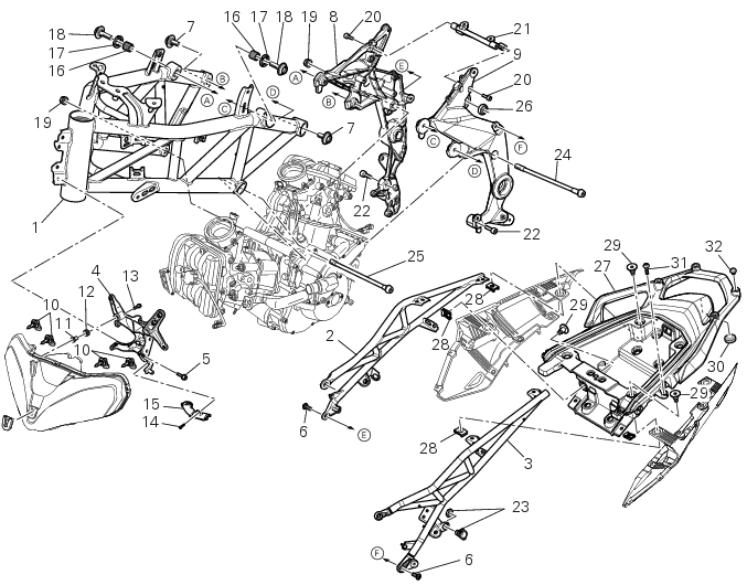
The structural component of the frame (2) is the rear subframe (3).
Both serve to support motorcycle superstructures and must therefore be in perfect condition.
The flow chart below illustrates the logical sequence in which the parts are to be removed from the motorcycle and gives a ref­erence to the section of the manual in which the removal procedure is described.
Removing of the headlight assembly
Remove the clamps (A) and release the front wiring branch of the light support (4).
Undo the screws (5) and remove the complete headlight assembly support (4).
Removal of the rear subframe
Undo the upper and lower screws (6) fixing the rear right (2) and left (3) subframe to the plates.
Remove the rear right and left subframes.
Undo screws (29) and remove the rear subframes (2) and (3) from the rear handgrab (27).
Removing the side plates
Loosen the four screws (20) that fix plates (8) and (9) to the bracket (21).
Undo the rear special screws (7) and the front special screws (18) that fix plates (8) and (9) to the frame (1).
Loosen ring nuts (17) and the adjusters (16).
 
 
Checking the frame
Check the dimensions of the frame against the dimensions shown here to determine whether it needs to be realigned or re­newed.
Important
Damaged frames must be changed, not repaired. Any work carried out on the frame can give rise to potential danger, infringing the requirements of EC directives concerning manufacturers' liability and general product safety.
Frame general dimensions (mm)
Reassembly of structural components and the frame
Check the presence of the clips (A) and (B) on frame (1), in the points indicated by the arrows.
Check the presence of the clips (28) and (B) on the rear subframes (2) and (3).
Apply recommended grease on the threads of the adjusters (16) and the ring nuts (17) having care not to have grease on the surface (C) of the adjusters.
Tighten the adjusters on the ring nut side opposite to that featuring flats until bringing the surfaces as close as possible as shown.
Start (form the frame external side) the adjusters (16) in the bushes (D) on frame (1).
Tighten to torque of 0.6 Nm ± 10% (Sect. 3 - 3, Frame torque settings) the adjusters (16), until they come out (on the opposite side) of at least 2 mm, as indicated.
Note
If at the specified torque the adjusters should not tighten properly, maybe the adjusters or the frame could be non-conforming.
 
Loosen the adjusters (16) until bringing the surfaces as close as possible to the bushes internal profiles (D), as shown.
 
Refitting the rear subframe
Install the rear right (2) and left (3) subframe on the plates.
Insert the upper and lower fixing screws (6) and tighten to the torque of 25 Nm± 5% (Sect. 3 - 3, Frame torque settings).
Place the rear handgrab (27) and the side panels on the rear subframes (2) and (3) and tighten the screws (29) to a torque of
18 Nm ± 10% (Sect. 3 - 3, Frame torque settings).
For the MTS 1200 S ABS model check the presence of the adhesive pads (A) in the indicated points of the rear handgrab (27) and that they are positioned so that the internal profiles are tangent to the protrusions (B) upper edges and that they are centred with respect to the protrusions vertical axes, as indicated.
Refitting the side plates
Place on the ring nuts (17) the tool 88713.3526 on which the torque wrench shall be applied.
Keep the adjusters (16) blocked and tighten to a torque of 100 Nm ± 5% (Sect. 3 - 3, Frame torque settings) the ring nuts (17).
Apply recommended grease to the screws (7), (18) and (20).
To join the plates (8) and (9) to the frame (1), tighten the rear (7) and front (18) special screws to a torque of 50 Nm ± 5% (Sect. 3 - 3, Frame torque settings).
Join the plates (8) and (9) with the bracket (21) by tightening the four retaining screws (20) to a torque of 25 Nm ± 5% (Sect. 3 - 3, Frame torque settings).
Refitting the headlight assembly
Place the headlight assembly (4) on the steering tube and lock it inserting the screws (5).
Tighten the screws (5) to a torque of 25 Nm ±10% (Sect. 3 - 3, Frame torque settings).
Spread the front wiring branch on the light support (4) and lock it with the clamps (A).
 
1