|
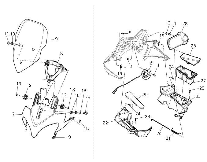
1
|
|
2
|
|
10
|
|
11
|
|
12
|
|
13
|
|
14
|
|
15
|
|
17
|
|
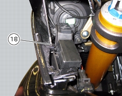
18
|
|
19
|
|
20
|
|
21
|
|
24
|
|
27
|
|
29
|