|
-
|
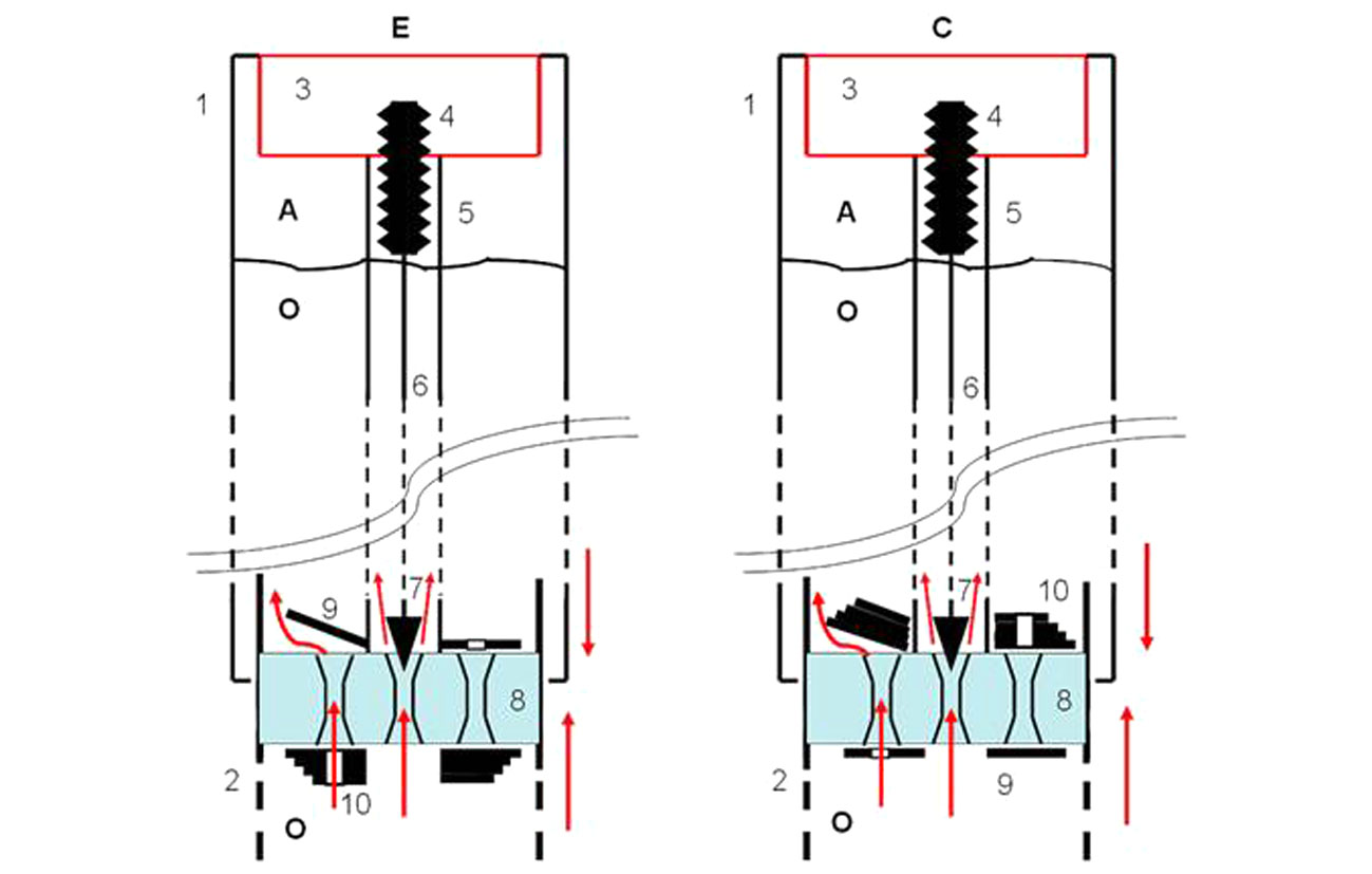
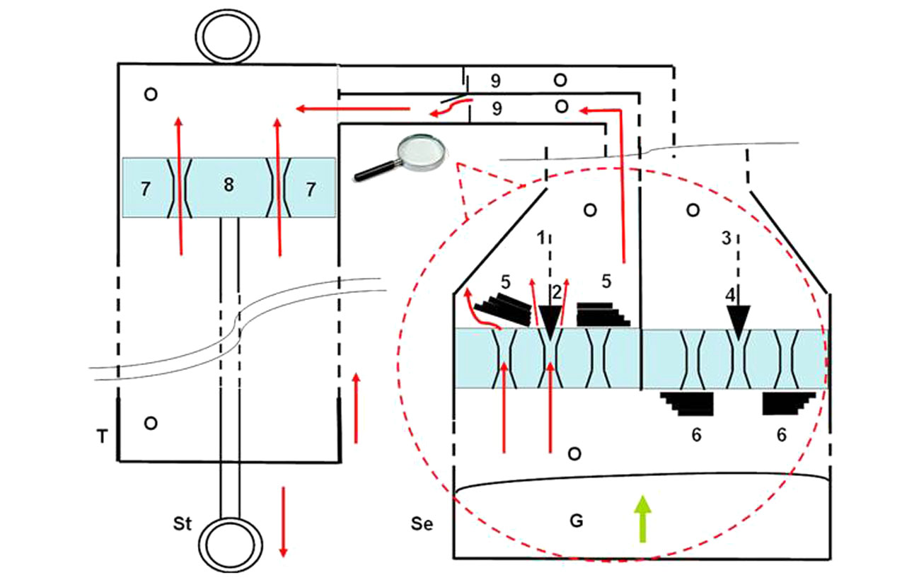
When the fork is compressed, the stanchion and piston move together and the oil must deflect the reeds in order to flow to the top of the piston (hydraulic damping).
|
|
-
|
As the conical needle moves up or down, it increases or decreases the aperture area of the By-pass at the centre of the piston. The oil flowing through this By-pass has no effect on the reeds. Raising the conical needle opens the By-pass and reduces the hydraulic damping effect. Conversely, lowering the conical needle increases the damping effect.
|
|
-
|
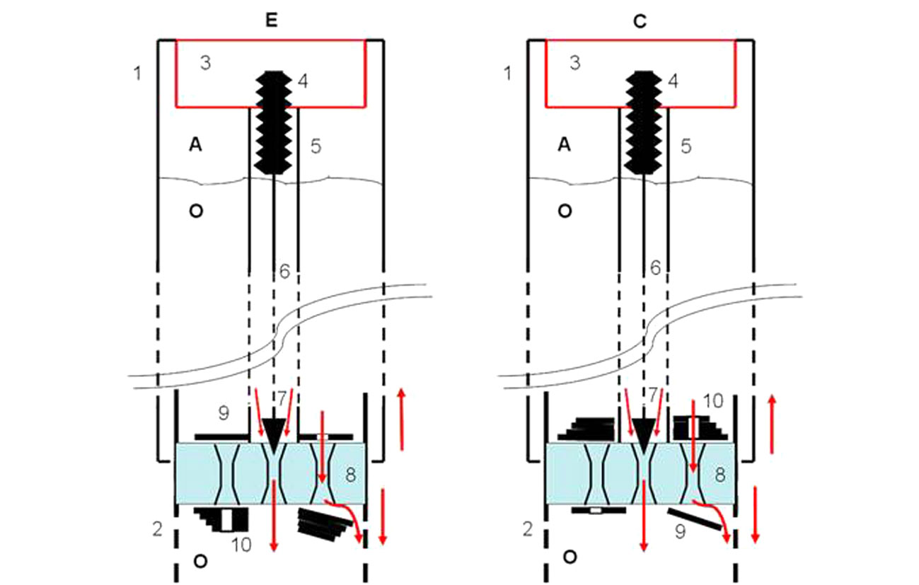
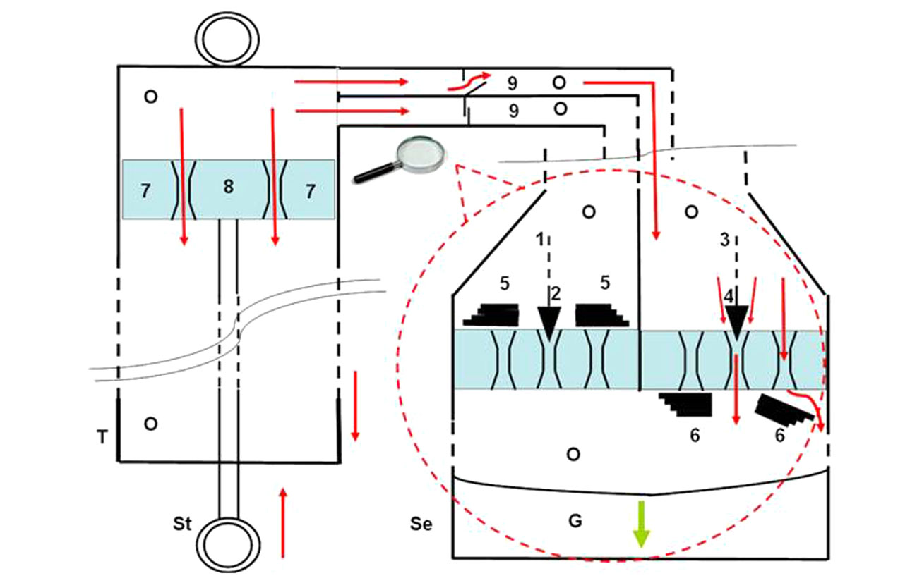
When the fork extends, the stanchion and piston move together and the oil must deflect the reeds in order to flow to the bottom side of the piston (hydraulic damping).
|
|
-
|
As the conical needle moves up or down, it increases or decreases the aperture area of the By-pass at the centre of the piston. The oil flowing through this By-pass has no effect on the reeds. Raising the conical needle opens the By-pass and reduces the hydraulic damping effect. Conversely, lowering the conical needle increases the damping effect.
|
|
A
|
|
O
|
|
1
|
|
2
|
|
4
|
|
5
|
|
8
|
|
10
|
|
A
|
|
O
|
|
1
|
|
2
|
|
4
|
|
5
|
|
8
|
|
10
|
|
5
|
|
6
|
|
7
|
|
8
|
|
5
|
|
6
|
|
7
|
|
8
|


|
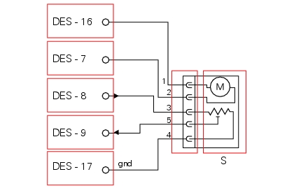
Dashboard: the error “DES front compression” (front suspension compression damping) is shown on the service display.
The EOBD warning light activates: |
||
|
Dashboard: the error “DES front compression” (front suspension compression damping) is shown on the service display. The EOBD warning light activates:
|
||
|
Dashboard: the error “DES front compression” (front suspension compression damping) is shown on the service display.
The EOBD warning light activates: |
||
|
Dashboard: the error “DES front compression” (front suspension compression damping) is shown on the service display.
The EOBD warning light activates:
|
|
Dashboard: the error “DES front rebound” (front suspension rebound damping) is shown on the service display.
The EOBD warning light activates: |
||
|
Dashboard: the error “DES front compression” (front suspension compression damping) is shown on the service display.
The EOBD warning light activates:
|
||
|
Dashboard: the error “DES front rebound” (front suspension rebound damping) is shown on the service display.
The EOBD warning light activates: |
||
|
Dashboard: the error “DES front rebound” (front suspension rebound damping) is shown on the service display.
The EOBD warning light activates:
|
|
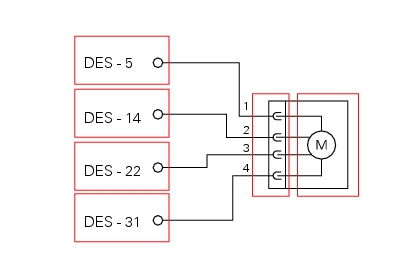
Dashboard: the error “DES rear compression” (rear suspension compression damping) is shown on the service display.
The EOBD warning light activates: |
||
|
Dashboard: the error “DES rear compression” (rear suspension compression damping) is shown on the service display.
The EOBD warning light activates:
|
||
|
Dashboard: the error “DES rear compression” (rear suspension compression damping) is shown on the service display.
The EOBD warning light activates: |
||
|
Dashboard: the error “DES rear compression” (rear suspension compression damping) is shown on the service display.
The EOBD warning light activates: |
|
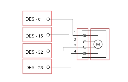
Dashboard: the error “DES rear rebound” (rear suspension rebound damping) is shown on the service display.
The EOBD warning light activates: |
||
|
Dashboard: the error “DES rear rebound” (rear suspension rebound damping) is shown on the service display.
The EOBD warning light activates:
|
||
|
Dashboard: the error “DES rear rebound” (rear suspension rebound damping) is shown on the service display.
The EOBD warning light activates: |
||
|
Dashboard: the error “DES rear rebound” (rear suspension rebound damping) is shown on the service display.
The EOBD warning light activates: |
|
||||
|
||||
|
||||
|
||
|
||
|