|
-
|
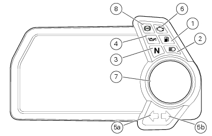
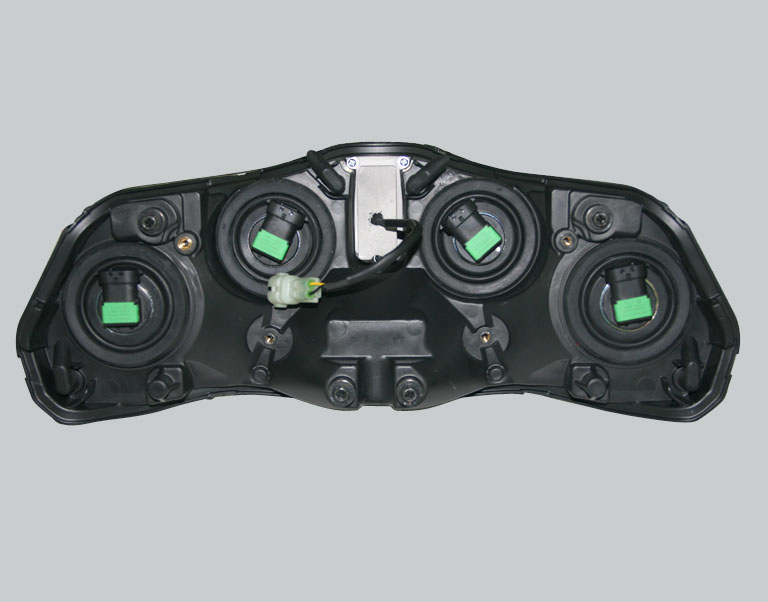
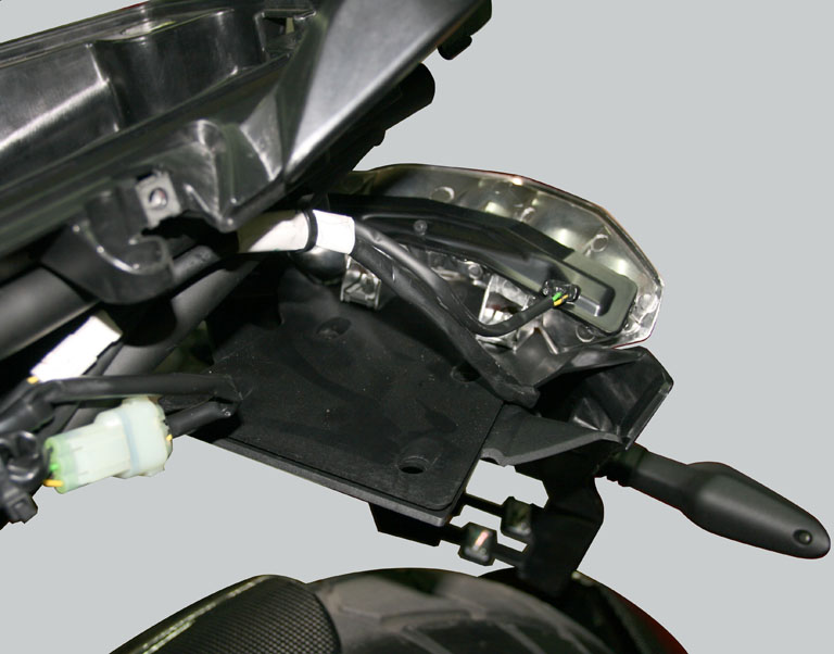
The Dash Board unit does not only display specific information of use to the rider, but is also connected to the sensors and actuators installed on the motorcycle. The unit makes the information received from the sensors available over the network and controls the actuators, also in response to orders received from other computers connected to the network. The unit's service display also visualises any vehicle electronic system faults
|
|
-
|
The Hands Free unit allows the rider to start the engine without inserting a conventional key into the ignition switch. This makes starting the motorcycle easier and quicker. The system also offers increased theft protection
|
|
-
|
The ECU manages the functions of the engine and also controls the ride by wire system. The ride by wire system modulates throttle valve aperture via an electric actuator coordinated by the ECU. The ECU receives a “torque demand” signal from a potentiometer linked to the throttle grip. Three different throttle valve aperture regimens are stored in the ECU, which make different maximum power values and different torque curves possible.
|
|
-
|
The Electronic Suspension unit adjusts the suspension set-up with electric actuators, rendering the use of conventional adjustment devices unnecessary. This is a passive adjustment system, meaning that it does not adapt automatically while the vehicle is in use
|
|
-
|
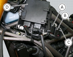
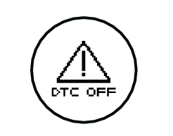
Like the Dash Board unit, the BBS is connected to sensors and actuators installed on the vehicle. The unit makes the information received from the sensors available over the network and controls the actuators, also in response to orders received from other computers connected to the network. It also has another fundamental function, as it gathers all the errors registered by the other computers due to specific faults. The software in the BBS also performs the DTC function, which regulates engine torque delivery to prevent wheelspin under acceleration. When replacing the BBS, if the motorcycle is equipped with electronic suspension or heated handgrips, the BBS must be correctly initialised with the DDS.
|
|
-
|
The ABS unit prevents wheel lockup during emergency braking. The ABS unit has its own fault diagnosis function, and is therefore equipped with its own specific diagnostic socket for connecting the DDS
|
|
-
|
A distributed system needs less sensors, substantially simplifying the electrical system, as information provided by certain sensors may be shared, rendering it unnecessary to provide duplicate sensors for each node.
|
|
-
|
|
-
|
The architecture of the network independent from the configuration of the system or, in other terms, the number of nodes (computers) connected to the network itself
|
|
-
|
DEVICE ECU the ECU node (engine control unit) is not recognised by the network or is not communicating with the network. In this case, the DDS may display the following messages relative to ECU function diagnosis: ECU counter, ECU no frame, ECU not compatible
|
|
-
|
DEVICE Dashboard the Dash Board node is not recognised by the network or is not communicating with the network. In this case, the DDS may display the following messages relative to Dashboard function diagnosis: Dashboard counter, Dashboard no frame, Dashboard not compatible
|
|
-
|
DEVICE Hands free the Hands Free node (facilitated keyless start system) is not recognised by the network or is not communicating with the network. In this case, the DDS may display the following messages relative to Hands Free function diagnosis: Hands free counter, Hands free no frame, Hands free not compatible
|
|
-
|
DEVICE DES the Electronic Suspension node (suspension with passive electronic adjustment) is not recognised by the network or is not communicating with the network. In this case, the DDS may display the following messages relative to Suspension function diagnosis: Suspension counter, Suspension no frame, Suspension not compatible
|
|
-
|
BBS/DTC DEVICE this message is transmitted by the engine control unit to the dashboard and indicates that the BBS is not recognised by the network or is not communicating with the network. In this case, the DDS may display the following messages relative to BBS/DTC function diagnosis: BBS/DTC counter, BBS/DTC no frame
|
|
-
|
Device SW compatibility error- UNKNOWN DEVICE the BBS does not recognise the network to which it is connected
|
|
-
|
|
-
|
|
-
|
|
-
|
|
|
||||||
|
|
||||||
|
|
||||||
|
|
||||||
|
-
|
The sinusoid voltage generated by each phase during each rotation of the rotor is at a higher frequency than with the unit installed on SBK models. This is why the alternator used on the Multistrada 1200 is known as a high-frequency unit. This characteristic make the following possible:
|
|
-
|
Consistent current intensity even at low engine speeds. This means that electrical power consumers can be powered and the battery charged even at idle speed
|
|
-
|
Lower current intensity at high engine speeds. This means that the voltage regulator is not activated, which would otherwise have to dissipate the excess power not absorbed by current consumers
|
|
-
|
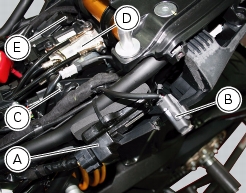
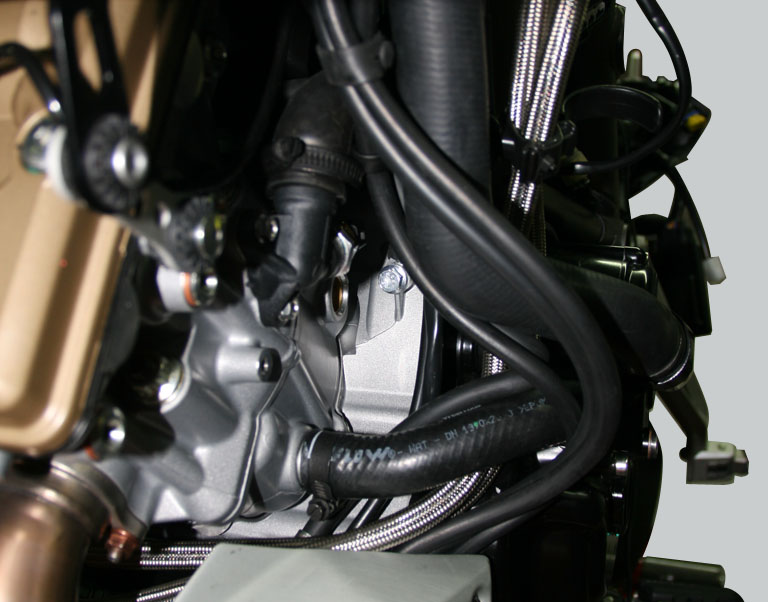
Check the integrity of the electrical circuit connecting the alternator to the regulator and the regulator to the battery (to carry out these tests, disconnect the battery cables and check the state of the electrical connections and cables and check for short circuits). Also check the ground connection of the circuit on the engine
|
|
-
|
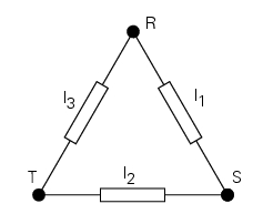
At an engine speed of 2,500 rpm, the alternating charging voltage measured between T – R, T – S and R – S with the alternator disconnected from the voltage regulator (“zero load”) must be between 40V and 50V. This measurement must only be made with a cold engine, and the alternator must only be disconnected from the voltage regulator in KEY OFF state. Replace the alternator if the voltage measured is incorrect.
|
|
-
|
Check the insulation relative to ground of each of the three terminals (the resistance between R - Ground, T - Ground and S - Ground must be infinite). If insulation is compromised, change the alternator windings
|
|
-
|
The battery state of charge must be checked first before checking the function of the voltage regulator. Battery state of charge is ideal if the voltage measured between the battery poles is between 12.2V and 12.7V. The battery must be disconnected from the motorcycle electrical system for this measurement. After reconnecting the battery to the motorcycle electrical system, turn the engine on and maintain an engine speed of 3,000 rpm. At this engine speed, the voltage measured at the battery poles must be between 14V and 15V. If the battery voltage measured is incorrect, replace the voltage regulator
|
|
Front LED turn indicators, commanded directly from Dash Board
|
||
|
Rear turn indicators with incandescent bulbs, commanded directly from BBS
|
||
|
License plate light with incandescent bulb commanded directly from Dash Board
|
||
|
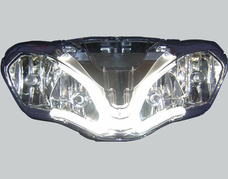
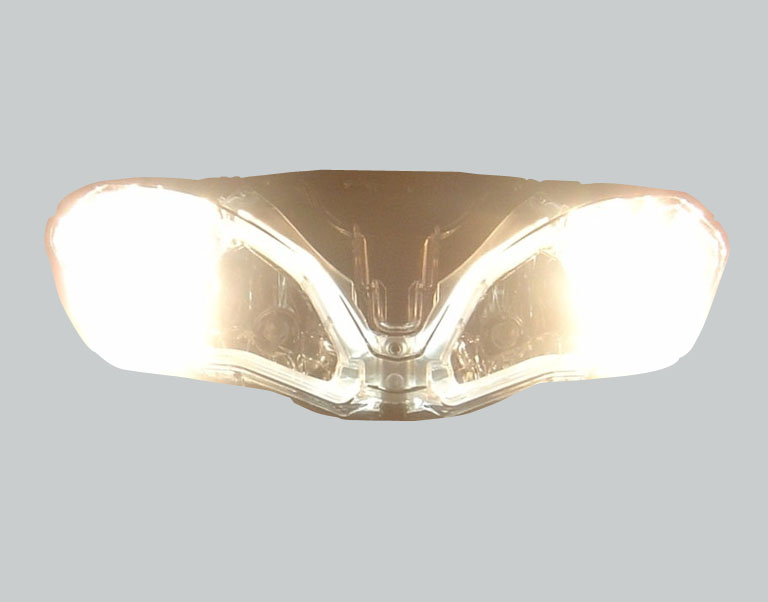
Low beam lights with incandescent bulbs, commanded by relay activated by Dash Board
|
||
|
High beam lights with incandescent bulbs, commanded by relay activated by Dash Board
|
||
|
Front and rear LED running lights, commanded directly from BBS
|
Device function may be tested using an external 12V power source
|
|
|
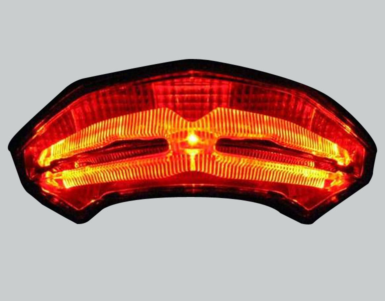
LED stop light, commanded directly from BBS
|
Device function may be tested using an external 12V power source
|