|
-
|
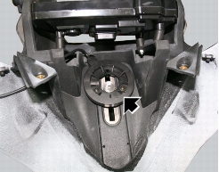
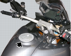
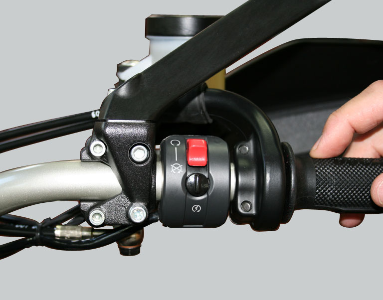
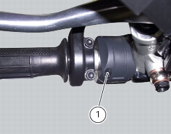
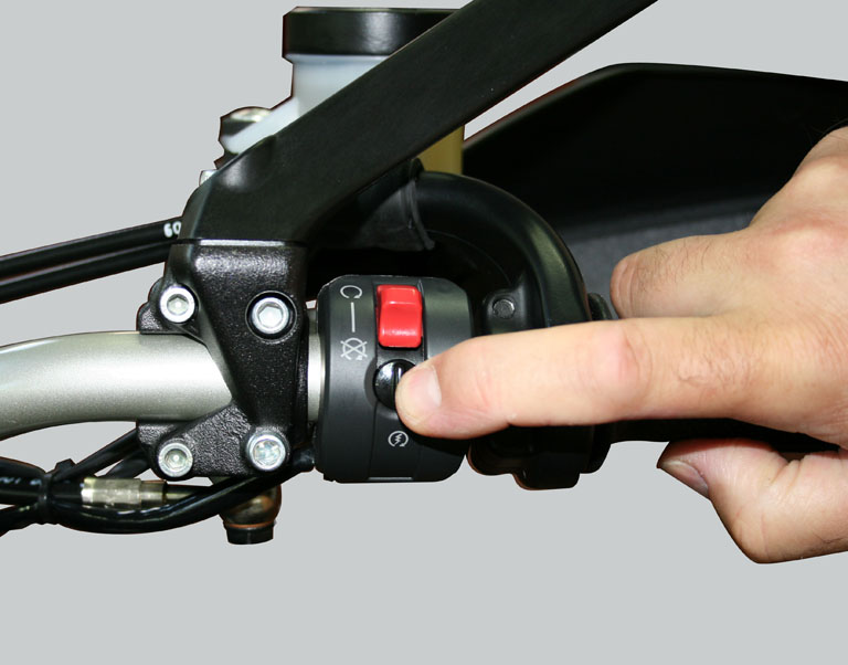
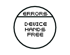
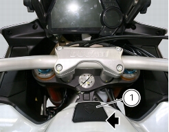
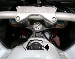
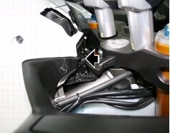
Hands free system with integrated button for switching the dashboard on and off and for locking and releasing the electric steering lock (henceforth indicated as “On/off button or switch”)
|
|
-
|
|
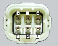
2
|
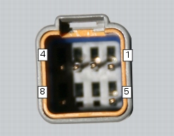
Hands free system ground – Black (BK);
|
|
3
|
Hands free relay coil command – Red/Yellow (R/Y);
|
|
4
|
CAN H line – Grey/Black (Gr/Bk);
|
|
5
|
CAN L line – Grey/Green (Gr/G);
|
|
6
|
Input for system on/off button on handlebar – Light Blue (Lb);
|

|
-
|
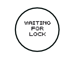
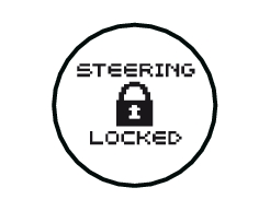
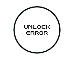
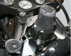
If the error occurred while engaging or disengaging the steering lock, check that the handlebar is fully turned to the left or right and try to engage or disengage the steering lock again.
|
|
-
|
If the error occurred while engaging or disengaging the steering lock, check that the lock pin can move freely and is unobstructed, then try to engage or disengage the steering lock again.
|


|
-
|
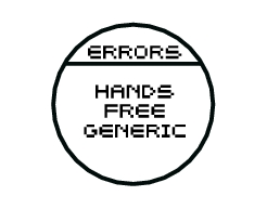
Check that the wires are not short circuited to one another, to Vcc or to ground.
Short circuit to Vdc: with the dashboard on, use a voltmeter to measure the voltage between the wire being tested and ground. Short circuit to ground: with the battery cables disconnected, use an ohmmeter to check for continuity between the wire being tested and ground. Open circuit: with the battery cables disconnected, use an ohmmeter to check that there is no continuity between the two ends of the wire being tested. |