|
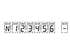
5 -
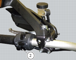
|


|
5
|
|
6
|
|
7
|
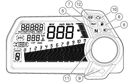
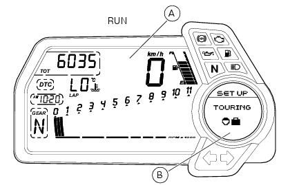
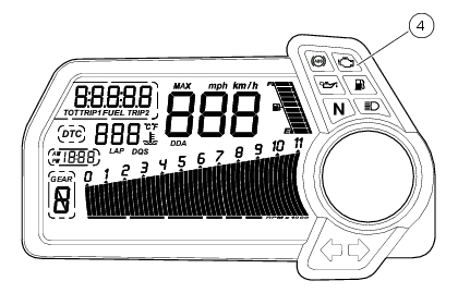
Engine oil pressure light (red).
Illuminates when engine oil pressure is too low. It must turn on at Key-On, but must turn off a few seconds after the engine has started. It may come on briefly if the engine is very hot, but should go out again as engine speed increases. |
|
8
|
Fuel warning indicator (amber yellow)
Comes on when fuel is low and 4 litres of fuel left in the tank. |
|
9
|
|
10
|
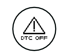
“Engine/Vehicle diagnosis - EOBD” indicator (amber yellow).
It turns on in the case of “engine” and/or “vehicle” errors and in some cases will lock the engine. |
|
1st threshold - no. RPM before the limiter threshold (*)
|
|
|
Rev limiter (limiter engaged due to overrevving) (*)
|
|
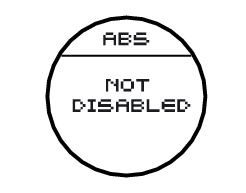
ABS disabled with the menu function “DISAB ABS” (**)
|
ABS enabled but not functioning yet
|
|
|
ABS disabled with the menu function “DISAB ABS”
|
ABS enabled but not functioning yet
|
|
|
ABS disabled with the menu function “DISAB ABS”
|
ABS disabled and not functioning due to a problem.
|
|


|
Warning light
|
||
|
|
||
|
|
||
|
|
||
|
|
||
|
|
||
|
|
||
|
|
||
|
|
||
|
|
||
|
|
||
|
|
||
|
|
||
|
|
||
|
|
||
|
|
||
|
|
||
|
|
||
|
|
||
|
|
||
|
|
||
|
|
||
|
|
||
|
|
||
|
|
||
|
|
||
|
|
||
|
|
||
|
|
||
|
|
||
|
|
||
|
|
||
|
|
||
|
|
||
|
|
||
|
|
||
|
|
||
|
|
||
|
|
||
|
|
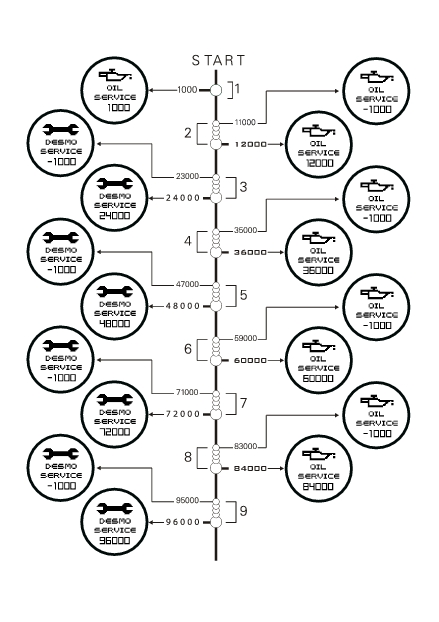
DES PRELOADER ADJUSTER
|

|
DESMO SERVICE
|
|||||


|
-
|
|
-
|
|
-
|
|
-
|
|
-
|
|
-
|
|
-
|
|
-
|
|
-
|
|
-
|
|
-
|


|
Off-road for very expert riders. It permits elevated rear wheel spin. It does not intervene in time on asphalt.
|
|||
|
Off-road for less experienced riders. Does not intervene in time on asphalt.
|
It is the default level for the “ENDURO” Riding Mode
|
||
|
It is the default level for the “SPORT” Riding Mode
|
|||
|
It is the default level for the “TOURING” Riding Mode
|
|||
|
“Very safe” riding together with the use of an 100HP ENGINE (maximum power 100 HP)
|
It is the default level for the “URBAN” Riding Mode
|
||

|
2
|


|
-
|
|
-
|


|
-
|