18 -
1
2
3
4
5
6
7
8
9
10
11
12
13
14
15
16
17
18
19
20
21
22
23
24
25
 Spare parts catalogue
Important
Bold reference numbers in this section identify parts not shown in the figures alongside the text, but which can be found in the exploded view diagram.
Removal of the licence plate holder
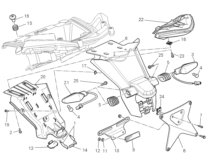
Undo the license plate holder fixing screws (16) collecting the vibration damper mounts (15).
Remove the clamps (A) and disconnect the tail light connector (B) from the main wiring.
Undo the screws (7) to remove the plate (8) from the license plate holder (6).
Note
For USA version, the plate (8) has a different shape.
Detach the number plate holder (6) from the splashguard (20) by undoing the three screws (19).
Raise the splash guard (20) from the license plate holder (6) paying attention to the internal wiring.
Disconnect wiring fastons (E) from the number plate light reeds.
Remove the fixing clamps (F) of the rear turn signals connectors (C) and disconnect the connectors (C) from the main wiring con­nectors (D).
Undo the screws (23) and remove the rear taillight from the license plate holder (6).
Refitting the licence plate holder
Check the presence of clips (17) on the license plate holder (6).
Refit the rear tail light (22) on the number plate holder (6) by starting and tightening the screws (23) to a torque of 3 Nm ± 10% (Sect. 3 - 3, Frame torque settings).
Connect the rear turn signal connectors (C) to the main wiring connectors (D).
Note
During the connection of the connectors (C) and (D) be careful to respect the indications on the identification labels on the cables: the RH (F) and LH (G) turn indicator wires can be distinguished by looking to the (“LH“ and “RH”) identification labels applied on the wires.
 
Connect the wiring fastons (E) to the number plate light reeds on the splashguard (20).
Place the wires between the pins on the number plate holder.
Fit the splash guard (20) on the license plate holder (6), paying attention not to press the wires underneath.
Tighten the screws (19) to a torque of 3 Nm ± 10% (Sect. 3 - 3, Frame torque settings).
Connect the rear turn indicator wires (H) and the tail lights wires (L) respectively to the rear turn indicator wiring (M) and the tail light wiring (N) coming from the number plate unit (6).
Bind the wires with ties in correspondence of the connectors as indicated.
Position the number plate unit (6) by putting the tied connectors between the LH side panel (P) and the rear handgrab (Q).
Note
During the operation, take care that the connectors wires do not tear because of rubbing against the LH subframe (R).
Check for the rubbers (15).
Tighten the number plate holder (6) by inserting the screws (2) and (16).
Tighten the screws (2) to a torque of 6 Nm ± 10% (Sect. 3 - 3, Frame torque settings) on screws (16).
Fit the plate (8) on the number plate holder (6), tightening the screws (7) to the specified torque of 6 Nm ± 10% (Sect. 3 - 3, Frame torque settings).
Connect the rear wiring (B) to the wiring and fit the ties (A): please refer to Sect. 6 - 1, Routing of wiring on frame.
 
1