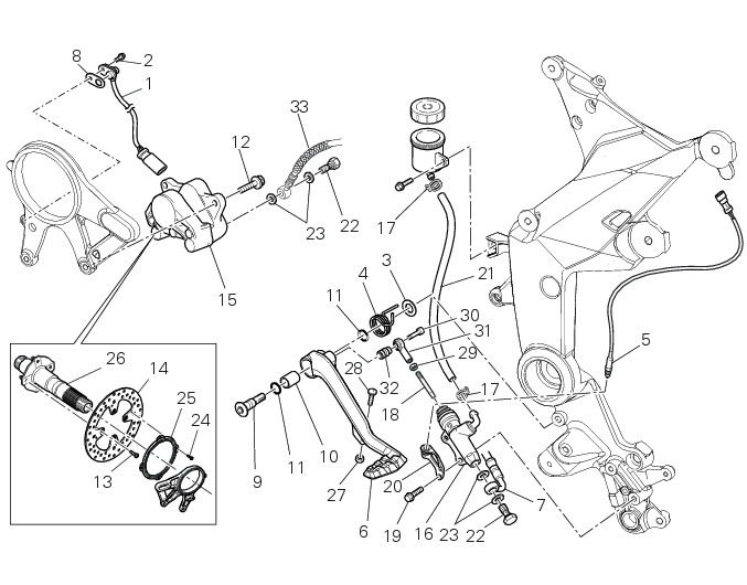
4 -
1
2
3
4
5
6
7
8
9
10
11
12
13
14
15
16
17
18
19
20
21
22
23
24
25
26
27
28
29
30
31
32
33
 Spare parts catalogue
Important
Bold reference numbers in this section identify parts not shown in the figures alongside the text, but which can be found in the exploded view diagram.
Removing of the rear brake control
Warning
The brake master cylinder manufacturer advises against servicing the brake master cylinder due to the safety critical nature of this component.
Incorrect overhaul can endanger the rider and passenger.
 
Maintenance operations on these units are limited to renewal of the following parts: control lever, fluid reservoir assembly and relative fasteners and master cylinder fasteners.
 
Note
For the ABS front braking system, also refer to Sect. 7 - 5, ABS system operating information, Sect. 7 - 6, System components, Sect. 7 - 7, ABS components maintenance.
 
Disconnect the rear stop switch (5) from the main wiring (Sect. 6 - 1, Routing of wiring on frame).
Undo the fixing screws of the rear brake pump (19).
Remove the rear brake pump (16) from the pushrod (18) and collect the fixing bracket (20) of the rear stop (5).
Undo the fixing pin (9) of the brake lever (6), collecting the spring (4).
Remove the brake lever (6) and collect the pin (9), the washer (3), the bush (10) and the O-ring (11).
Undo the special screw (22) from the pump (16) and remove the pipe grommet (17); slide the pipe (7) recovering the gaskets (23) and the pipe (21).
Remove the rear brake pump (16) from the motorcycle.
 
Disassembly of the rear brake control
The brake master cylinder is supplied only as a complete unit; internal components cannot be replaced.
To disassemble the master cylinder's outer parts, follow the indications given in the exploded view at the beginning of this Sec­tion.
If the bush (10) inside the brake pedal (6) needs to be replaced, grease the external surface and fit the new bush using a press to insert it. The bush must be placed at 2 mm from the pedal external face.
To disassemble the various parts of the system, refer to the exploded view at the beginning of this chapter.
Warning
After performing an operation on the rear brake control, check the brake pedal position following the instructions detailed in Sect. 4 - 3, Adjusting the position of the gear change and rear brake pedals.
Refitting the rear brake control
If previously removed, apply prescribed threadlocker to the screw (30), fit the brake master cylinder control rod (31) with spacer (32) and tighten screw (30) to a torque of 10 Nm ± 10% (Sect. 3 - 3, Frame torque settings).
Check that the adjuster screw (27) and nut (28) are positioned at the distance apart shown.
Apply grease the inner surface of the bush (10) and threadlocker on the pin (9).
Fit the O-ring (11) in the pin (9).
Insert the pin (9) on the brake lever (6), place the other O-ring (11) and the washer (3).
Refit the pipe (7), placing the gaskets (23) in both sides of the coupling and tighten it with the special screw (22), and the pipe (21) fixing it with the pipe grommet (17).
Tighten the special screw (22) to a torque of 23 Nm ± 10% (Sect. 3 - 3, Frame torque settings).
 
Note
Pay special attention to the pipes (7) and (21) orientation on the rear brake pump (16).
Apply the recommended threadlocker on the pin (9).
Fit the brake lever (6) with spring (4) inserting the pin (9).
Place the end (A) of the spring (4) as shown in figure.
Tighten the pin (9) to a torque of 23 Nm ± 10% (Sect. 3 - 3, Frame torque settings).
Refit the fixing bracket (20) of the rear stop (5) on the rear brake control (6).
Apply the recommended threadlocker on the screws (19).
Position the rear brake pump (16) on the vehicle inserting the fixing screws (19).
Insert the rod (18) inside the pump (16), after applying the recommended grease.
Tighten the screws (19) to a torque of 10 Nm ± 10% (Sect. 3 - 3, Frame torque settings).
Connect the rear stop switch (5) to the main wiring.
In order to fit the pipes (7), (21) and the retaining clamps, follow the instructions in Sect. 7 - 6, Flexible wiring/hoses positioning.
 
Removal of the rear brake calliper
Important
The brake manufacturer advises against any servicing of the internal components of brake callipers or the master cylinder. Incor­rect overhaul of these critical safety components can endanger rider and passenger safety.
 
Before removing the parts in question, you must first carry out the following operations:
 
Note
For the ABS front braking system, also refer to Sect. 7 - 5, ABS system operating information, Sect. 7 - 6, System components, Sect. 7 - 7, ABS components maintenance.
 
Unscrew and remove the special screw (22) fixing the pipes (33) to the rear brake calliper and the corresponding couplings (23).
Remove tube (33).
 
Undo the two fixing screws (12) of the rear brake calliper (15) to the calliper holder bracket and remove the brake calliper (15).
If it is necessary to remove the calliper holder bracket (A) refer to Sect. 7 - 13, Removal of the rear wheel eccentric hub and rear wheel axle.
Note
To replace the brake pads follow instructions in the paragraph “Checking brake pad wear and changing brake pads” (Sect. 4 - 3).
 
To remove the speed sensor (1), undo the fixing screw (2) paying attention to the airgap spacer (8).
Only the following parts should be renewed:
-
-
 
Refer to the exploded view at the beginning of this section for indications on renewal of the above components.
Removal of the rear brake disc
Remove the rear eccentric hub (Sect. 7 - 13, Removal of the rear wheel eccentric hub and rear wheel axle).
Undo and remove the four fixing screws (13) of the brake disk to the wheel axle and remove the rear brake disk (14).
Loosen the four screws (24) and remove the rear phonic wheel (25).
The brake disc must be perfectly clean, with no rust, oil, grease or other dirt and no deep scoring.
To check the wear limit of the brake disk refer to Sect. 3 - 1.1, Hydraulic brakes.
Place the rear brake disc (14) on the rear wheel shaft (P), by orienting the bevelled edges (A) faced upwards.
Fix the disc by starting the screws (13) with prescribed threadlocker.
Note
Make sure to centre the screw heads in the relevant seats on the brake discs.
 
Tighten the screws (13) to a torque of 27 Nm± 10% (Sect. 3 - 3, Frame torque settings), in the sequence 1-2-3-4.
Position the phonic wheel (25) on the brake disc (14) by orienting it as shown in figure.
Fix the phonic wheel (25) by starting the screws (24) with pre-applied threadlocker.
Tighten the screws (24) to a torque of 5 Nm ± 10% in a crossed-pattern sequence.
Refit the rear eccentric hub as described in Sect. 7 - 13, Removal of the rear wheel eccentric hub and rear wheel axle.
Refitting the rear brake calliper
When replacing the brake pipes (33) or removing one of the rear braking system components, pay special attention to the position of the couplings on the pump and the calliper.
Warning
If incorrectly positioned, the hose can affect brake operation and foul moving parts. Position the hose as shown in the figure.
Remember to fit the copper faced sealing washers (23) to the hose end fitting when reconnecting the brake pipe to the brake calliper (15).
 
After orientating the fitting, lock the special screw (22) to a torque of 23 Nm± 10% (Sect. 3 - 3, Frame torque settings).
If the speed sensor (1) was removed, fit it on the calliper holder bracket (A) with the spacer (8) and tighten the screw (2) to a torque of 10 Nm± 10% (Sect. 3 - 3, Frame torque settings).
Note
The gap between the sensor (1) and the brake disc fixing screw must be within 0.6 to 2.2 mm.
 
If it is necessary to remove the calliper holder bracket (A) in order to refit it, see Sect. 7 - 13, Refitting the rear wheel eccentric hub and rear wheel axle.
Insert the rear brake calliper (15) on the brake disk, aligning it with the holes of the calliper mounting bracket (A).
Grease the screws (12) and tighten to the torque of 25 Nm± 5% (Sect. 3 - 3, Frame torque settings).
In order to fit the pipe (33), the speed sensor (1) and the retaining clamps follow instructions in Sect. 7-6, Flexible wiring/hoses positioning.
 
 
1