13 -
1
2
3
4
5
6
7
8
9
10
11
12
13
14
15
16
17
18
19
20
21
22
23
24
25
26
27
28
29
30
31
 Spare parts catalogue
Important
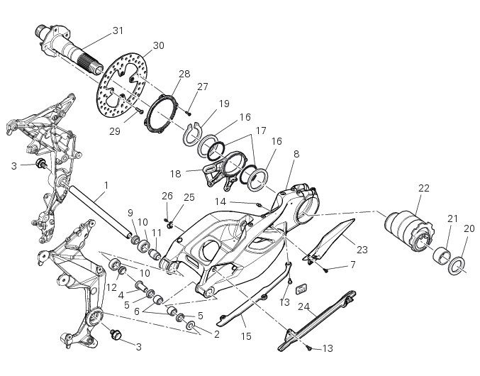
Bold reference numbers in this section identify parts not shown in the figures alongside the text, but which can be found in the exploded view diagram.
Removal of the rear wheel eccentric hub and rear wheel axle
Before removing the eccentric hub, you must first remove the parts listed below.
 
Slacken off the screws (A).
Remove the spacer (20) and the inner ring (21) on the chain side and remove the wheel shaft (31) with the brake disc (30) from the opposite side.
 
Remove the circlip (19) on the wheel side of the eccentric hub.
Remove the washer (16) and the calliper holder bracket (18) with the O-rings (17).
Remove the other washer (16).
Withdraw the eccentric hub (22) from the chain side of the swingarm.
Note
The rear hub is a component particularly critical to the dynamic safety of the motorcycle. under no circumstances may the internal components of the hub be serviced or repaired. The hub may be ordered as a complete assembly, spare part No. 756.2.013.1A.
Refitting the rear wheel eccentric hub and rear wheel axle
Refitting is the reverse of removal, with attention to the following points.
If the calliper bracket locating pin (14) was removed, apply the recommended threadlocker on reassembly.
Tighten the pin (14) to the torque of 33 Nm ± ±5% (Sect. 3 - 3, Frame torque settings).
Before refitting apply some recommended grease to the eccentric hub (22) external surface.
Fit the first washer (16).
Apply grease on rings (17) and place them in their seat of the plate (18). Place the plate (18) on the swingarm: the shaft (14) must remain inside the plate (18).
Refit the other washer (16).
Place the circlip (19) with the sharp edge faced outwards.
Check that the eccentric hub (22) with respect the swing arm (8) features the horizontal axis (D) of the hub bore (B) under the horizontal axis (C) of the hub seat.
Apply an even coating of the recommended grease in the areas (A) of the axle (31).
Insert the rear wheel stub axle (31) in the hub.
Ensure the stub axle (31) is seated in the hub.
Fit the inner ring (21) on the wheel shaft (31).
Insert the inner ring (21) in the hub.
Apply the recommended grease to the screws (A) and tighten to the torque of 35 Nm±5%(Sect. 3 - 3, Frame torque settings) following the sequence 1-2-1.
 
Set the chain tension as described in Sect. 4 - 3 “Adjusting the chain tension”.
Removal of the swingarm
Before removing the parts in question, you must first carry out the following operations:
 
 
Remove the rear wheel eccentric hub as described in chapter “Removal of the rear wheel eccentric hub and rear wheel axle” of this section.
Undo the screw (A) and remove the upper pipe grommet (B); release the rear brake pipe and the rear speed sensor cable from the swingarm, undoing the screws (26) and retrieving the cable grommets (25).
You can check the play in the swingarm bearings while the swingarm (8) still installed on the motorcycle frame
Grasp the rear of the swingarm (8) and try to move it in the four directions shown by the arrows.
Any abnormal movement is a sign of worn bearings that could cause instability when riding.
To check the free play of the support bearings, refer to Sect. 7 - 1, Wheel bearings.
Once the play in the swingarm bearings has been checked, the swingarm (8) may be removed from the motorcycle.
Keep the swingarm shaft (1) blocked with the screws (3) on the bike LH side and loosen at the same time the screw (3) on the opposite side: keep washer (2).
Using the pad 88713.1074, fully extract the swingarm pivot.
Remove the swingarm (8) assembly from the frame.
Undo the screw (13) to remove the lower chain slider (15) from the swingarm (8).
Undo the screws (7) to remove the chain guard (23) from the swingarm (8).
Undo the screws (13) to remove the upper chain slider (24) from the swingarm (8).
Inspecting the swingarm pivot shaft
Before refitting the swingarm pivot shaft (1), check it carefully for distortion.
Roll the pin on a reference surface and measure maximum distortion using a feeler gauge (Sect. 3 - 1.1, Rear wheel).
Overhauling the rear swingarm
Inside the swingarm (8), in correspondence with the pivot point on the frame, there is a pair of ball bearings (10) and a spacer (11) on the RH side, and a pair of roller bearings (6), with sealing rings (5), on the LH side.
To change the bearings, proceed as follows.
Remove the spacers (12) and (9) fitted on the RH side of the swingarm, and the bush (4) on the LH side.
Remove the ball bearings (10), sealing rings (5) and roller bearings (6) with a suitable punch and press. Support the swingarm and take care not to damage the bearing bores.
Important
Once removed, the bearings (10), sealing rings (5) and roller bearings (6) must not be reinstalled.
Heat the entire swingarm up to 150 °C while supporting its weight adequately.
Insert the new roller bearings (6) in the punch tool with code 88713.1068 and install them into the bore on the left-hand side of the swingarm, working from the outside.
Drive them in until the tool is fully seated against the swingarm.
Use the same tool to fit the new sealing rings (5), positioned as shown in the sectional view, so that they seat against the newly installed roller bearings.
To install the ball bearing (10) you will need the tool with part no. 88713.2409 with:
(A) – drift for internal bearings;
(B) – drift for external bearings;
(C) – guide pin.
 
Fit a new bearing (10) and the internal spacer (11) onto the punch tool (A) and install it on the inner side of the swingarm RH mounting.
Insert the guide pin (C) into the previously mounted roller bearings and insert the other end in the bore in the tool (A).
Drive the bearing (10) fully into the swingarm.
Fit the other new bearing (10) at the outer end of tool (A).
Using tool (A) as a stop, use tool (B) to drive the external bearing up against spacer (11): remove the tools.
Before refitting the swingarm (8), grease the ball bearings (10), the roller bearings (6) and the sealing rings (5) with the recom­mended grease.
Refit the shims (12) and (9) from the right-hand side of the swingarm (8) and refit the bush (4) from the left-hand side.
Refitting the swingarm
Apply the recommended threadlocker to the screws (7) and (13).
Install the chain guard (23) in the swingarm opening (8), and fasten it with the screws (7). tighten the screws (7) to a torque of
5 Nm ± 10% (Sect. 3 - 3, Frame torque settings).
Install the upper chain slider (24) in the swingarm slot (8), and fasten with the screws (13). tighten the screws (13) to a torque of 5 Nm ±10% (Sect. 3 - 3, Frame torque settings).
Install the lower chain slider (15) on the swingarm (8), fastening it with the screws (13). tighten the screws (13) to a torque of 5 Nm ±10% (Sect. 3 - 3, Frame torque settings).
Place the rear brake pipe and the rear speed sensor cable on the swingarm by starting the screws (26) of the cable grommets (25).
Refit the upper pipe grommet (B) by starting the screws (A).
Tighten screw (A) to a torque of 5 Nm ± 10% and screw (26) to a torque of 8 Nm ± 10% (Sect. 3 - 3, Frame torque settings).
Locate the swingarm (8) on the frame.
Lubricate with recommended grease the swingarm shaft (1) with the screw (3) and insert it fully home on the frame.
On the bike opposite side fix the swingarm shaft (1) with the screw (3) after having lubricated it with recommended grease, and fit the washer (2) between frame and swingarm.
Tighten the screw (3) to the torque of 72 Nm ± 5% (Sect. 3 - 3, Frame torque settings).


1