


|
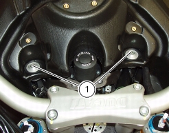
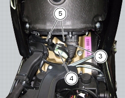
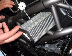
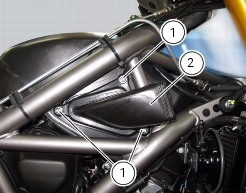
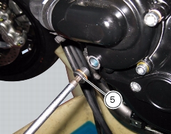
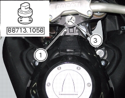
Remove the airbox without disconnecting the throttle cables and support it adequately
|
|
|
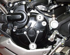
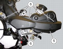
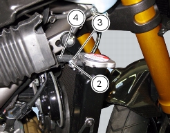
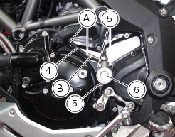
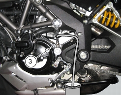
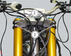
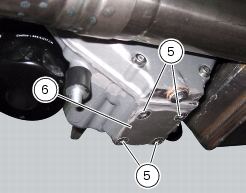
Undo the upper fixing screws of the timing system belt plate covers
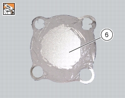
|
|

|
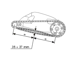
0.13 to 0.18 mm
|
|
|
0.10 to 0.25 mm
|
|
|
0.13 to 0.18 mm
|
|
|
0.10 to 0.25 mm
|
|
|
0.05 to 0.10 mm
|
|
|
0.05 to 0.15 mm
|
|
|
0.05 to 0.10 mm
|
|
|
0.05 to 0.15 mm
|
|