|
-
|
|
-
|
|
D
|
|
10
|
|
18
|
|
25
|
|
34
|
|
51
|
|
55
|
|
59
|


|
-
|
If the throttle valve aperture is below a specific threshold, the base quantity of fuel injected is determined using a strategy denominated 'speed-density' (engine speed-intake manifold pressure). There is therefore one base fuel quantity map with coordinates correlating the quantity of fuel injected with engine speed-pressure for cylinder 1 (horizontal) and another for cylinder 2 (vertical)
|
|
-
|
If the throttle valve aperture is over a specific threshold, the base quantity of fuel injected is determined using a strategy denominated α-n (throttle valve aperture angle-engine speed). There is therefore one base fuel quantity map with coordinates correlating the quantity of fuel injected with engine speed-throttle valve aperture for cylinder 1 (horizontal) and another for cylinder 2 (vertical)
|
|
-
|
At intermediate throttle valve apertures between the two thresholds described above, the base quantity of fuel injected is determined by applying the two strategies simultaneously
|
|
-
|
smooth torque delivery, as the ECU filters the signal received from the APS. As there is no direct connection with metal cables between the throttle grip and the throttle valve, any spurious movement of the throttle grip itself due, for example, to unevenness in the road surface straining the arms and hands of the rider, have no direct or immediate effect on engine delivery.
|
|
-
|
improved management of different engine operating states. As the ECU controls the aperture of the throttle valves, the ECU itself can determine the air flow into the engine independently of the actual throttle grip position set by the rider. This strategy defines three different regimens for throttle valve aperture (150 hp Hard, 150 hp Soft and 100 hp) that may be selected by the user without modifying the calibration of the engine control unit (in other terms, the quantity of fuel injected and the ignition advance, which are defined solely in relation to the 150 hp Hard throttle valve aperture regimen).
|
|
-
|
|
-
|
|
-
|
|
-
|
|
-
|


|
-
|
ageing of the components of the cylinder unit, resulting in deviation from rated specifications (valve clearance, encrustation in combustion chamber and on valves, cylinder-piston seal integrity, variations in intake and exhaust gas flow)
|
|
-
|
fault of one or more elements influencing the combustion process or mixture production process (such as induction anomalies, injector malfunction, non-conforming fuel pressure etc.)
|
|
-
|
When the engine is switched off, the ECU remains powered for a predetermined number of seconds (power latch or self-shut down function), during which the real time self-adaptive parameters are memorised in the ECU, updating the long term parameters.
|
|
-
|
When the engine is switched on, the ECU retrieves the long term parameters from its memory and uses them, updating them continuously. These therefore become the real time parameters.
|

|
-
|
|
-
|
|
-
|
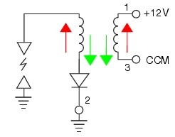
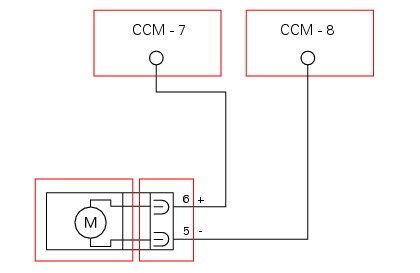
If the engine runs on one cylinder only and there is no spark at one of the two spark plugs, try swapping the coils. If the fault (no spark) follows the coil, the coil itself is faulty. If the fault does not follow the coil, the relative control circuit is faulty.
|
|
-
|
If the engine runs unevenly (backfires and torque delivery is uneven), check that PIN 2 on the primary coil winding is grounded correctly. If necessary, replace the coils as the respective internal diode may be damaged (short circuited).
|

|
-
|
|
-
|
|
-
|
|
-
|
|
-
|
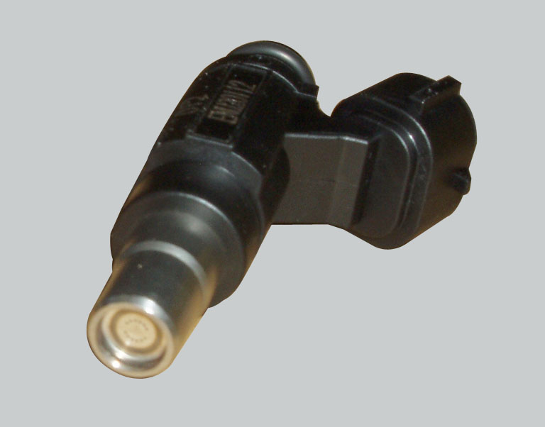
If the engine is running on once cylinder only and one of the injectors does not open, try swapping the injectors. If the fault (no injector opening) follows the injector, the injector itself is faulty. If the fault does not follow the injector, the relevant control circuit is faulty.
|
|
-
|
If the engine runs irregularly, check the pressure and flow rate in the fuel circuit (see paragraph “Fuel system circuit“ of this section) and check that the injectors atomise the fuel correctly.
|
|
-
|
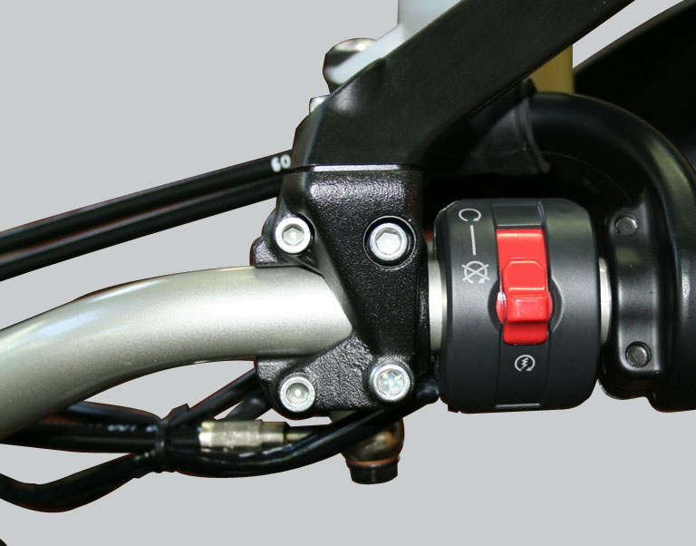
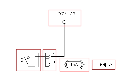
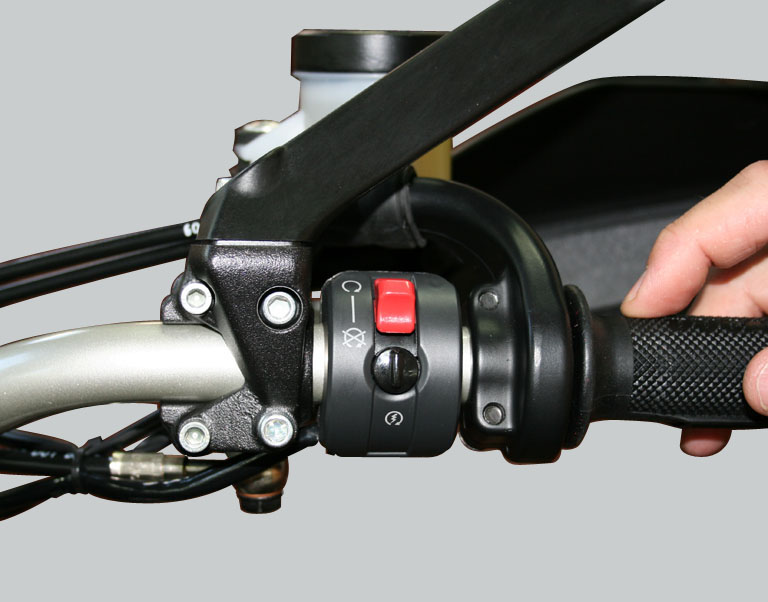
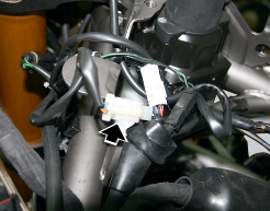
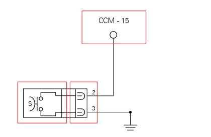
If power supply voltage (12 V – KEY ON) is present on PIN 3 of the switch (if not, consult Sect. 6 - 7 paragraph “The Hands Free module”)
|
|
-
|
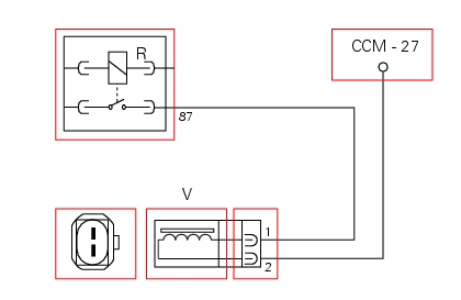
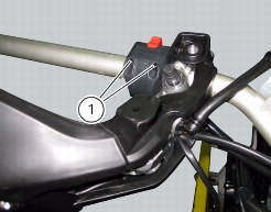
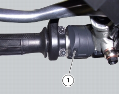
Integrity of Stop Engine switch. In the switch's two different positions, the resistance at its contacts (PIN3 and PIN 4) must be zero in one position (continuity) and infinite in the other (open circuit)
|
|
-
|

|
-
|
|
-
|
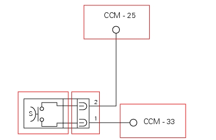
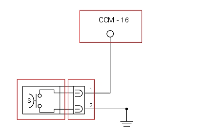
Integrity of the start button. In the button's two different positions, the resistance at its contacts (PIN 1 and PIN 2) must be zero (depressed - continuity) or infinite (released - open circuit).
|
|
-
|

|
Gearbox in neutral – any side stand and clutch lever position
|
|
|
Gear engaged – side stand retracted – clutch lever pulled
|
|
-
|
Integrity of the clutch button. When the clutch lever is operated (pulled and released), the resistance on the button contacts (PIN 1 and PIN 2) must be zero in one position (continuity) and infinite in the other (open circuit)
|
|
Gearbox in neutral – any side stand and clutch lever position
|
|
|
Gear engaged – side stand retracted – clutch lever pulled
|
|
-
|
Integrity of the side stand button. When the side stand is used (extended and retracted), the resistance on the button contacts (PIN 2 and PIN 3) must be zero in one position (continuity) and infinite in the other (open circuit)
|

|
-
|
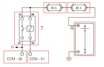
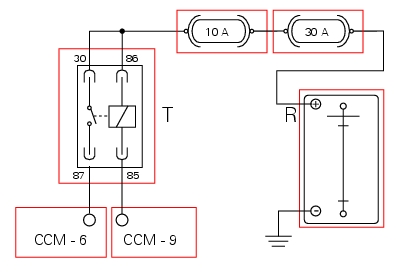
Relay function. After removing from its mounting, apply 12 V power to PIN 85 and PIN 86 of the relay and check that PIN 87 and PIN 30 close (continuity between pins)
|

|
-
|
Throttle valve actuator motor relay malfunction (no specific fault indicated by DDS): check integrity of the fuses, electrical circuit and electrical connections and check relay function. After removing from its mounting, apply 12 V power to PIN 85 and PIN 86 and check that PIN 87 and PIN 30 close (continuity between pins).
|
|
-
|
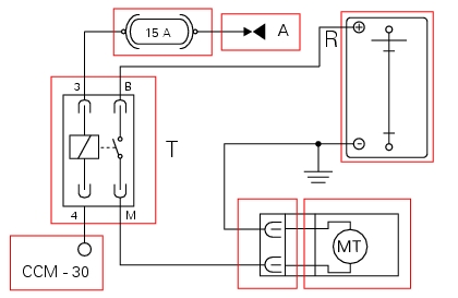
If power supply voltage (12 V - KEY-ON) is present on PIN 3 of the starter motor relay (if not, consult the paragraph “Hands free”) and check the integrity of the 15A fuse
|
|
-
|
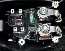
Integrity of the starter motor relay. After removing the relay, when 12 V power is applied to PIN 3 and PIN 4, the contacts should close (continuity between PIN B and PIN M)
|
|
-
|

|
-
|
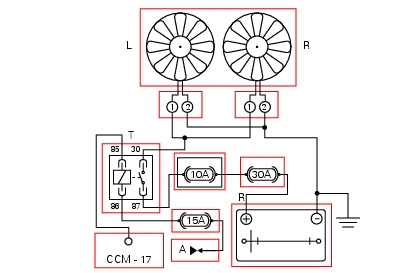
If power supply voltage (12 V – KEY ON) is present on PIN 86 of the radiator fan relay (if not, consult the paragraph “Hands free”)
|
|
-
|
Radiator fan function. After removing from its mounting, apply 12 V power to PIN 85 and PIN 86 and check that PIN 87 and PIN 30 close (continuity between pins).
|
|
-
|
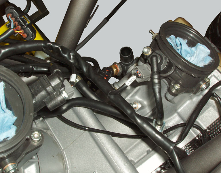
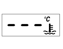
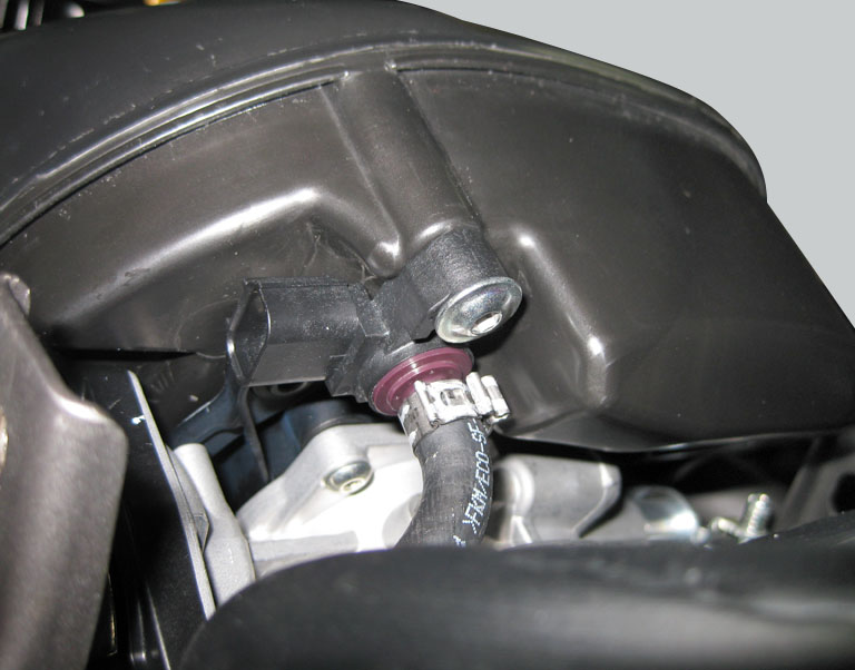
The engine temperature sensor (see “Engine temperature sensor of this section”).
|
|
-
|
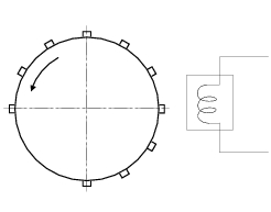
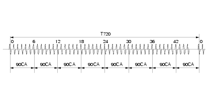
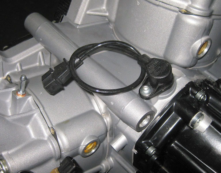
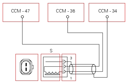
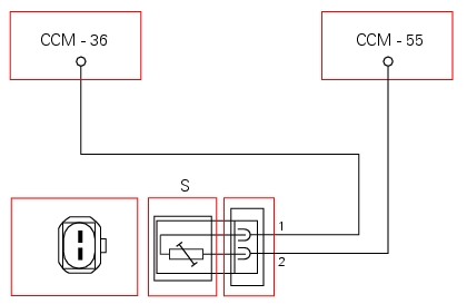
Engine speed sensor malfunction (no specific fault indicated by DDS): check the integrity of the electric circuit and check that the resistance between PIN 1 and PIN 2 of the winding is between 774 and 946 Ohm at an ambient temperature of 20°C.
|
|
-
|
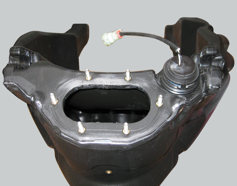
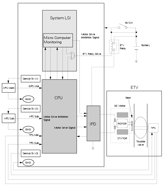
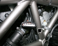
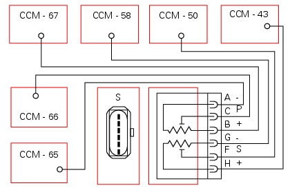
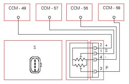
For safety reasons, the sensor contains two potentiometers (a main potentiometer – MAIN – and a secondary potentiometer – SUB) with independent 5V power and ground
|
|
-
|
Incorrect electrical characteristics: check integrity of electric circuit and electrical connections. If the above measures do not resolve the fault, contact Ducati.
|
|
-
|
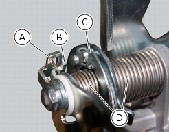
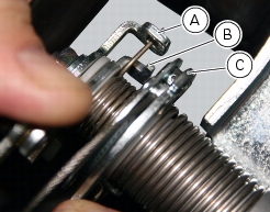
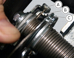
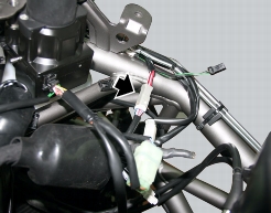
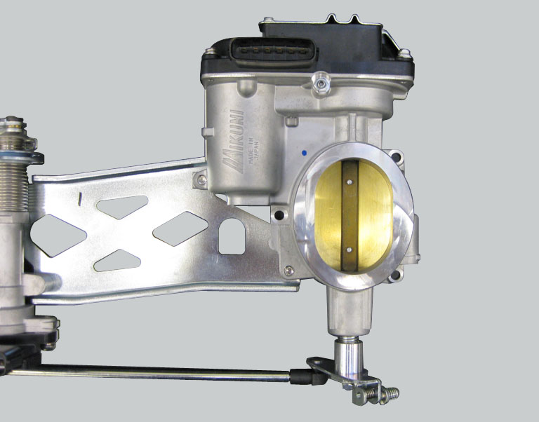
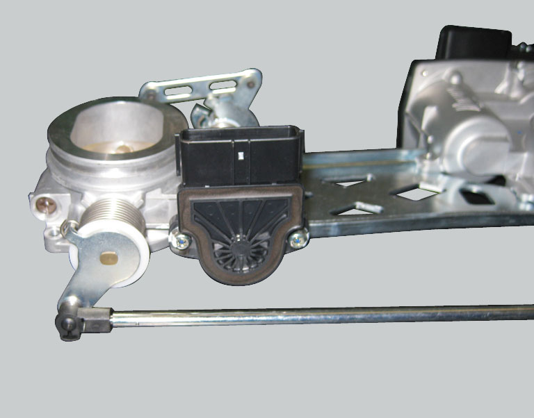
That the metal cables operating the roller connected to the accelerator position sensor are correctly adjusted so that the roller can reach both the fully closed (throttle grip released) and fully open (throttle grip fully twisted) positions
|
|
-
|
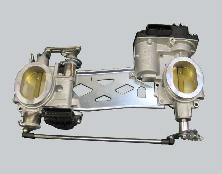
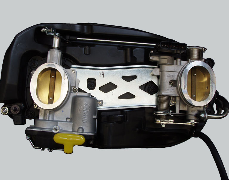
The sensor sends information to the engine control unit relative to the position of the vertical cylinder throttle valve and, as a consequence, of the horizontal cylinder throttle valve, which is connected to the former by a link rod
|
|
-
|
For safety reasons, the sensor contains two Hall effect sensing elements (a main element – MAIN – and a secondary element – SUB). The two potentiometers share the same power and ground
|
|
-
|
Incorrect electrical characteristics: check integrity of electric circuit and electrical connections. If the above measures do not resolve the fault, contact Ducati.
|
|
-
|
|
-
|
|
-
|

|
-
|
|
-
|
The fuel quantity injected is determined using the α-n strategy only.
|
|
-
|
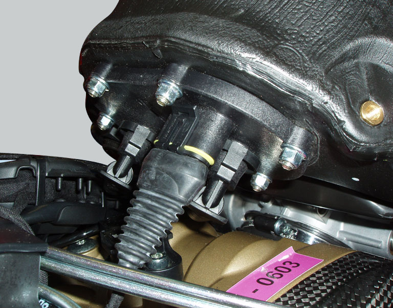
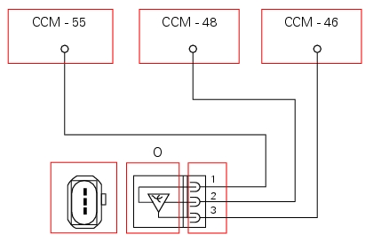
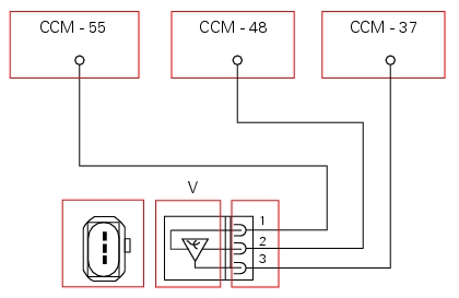
Absolute pressure sensor 1 (cylinder 1 - horizontal) and/or Absolute pressure sensor 2 (cylinder 2 - vertical), open circuit: check integrity of electric circuit and electrical connections.
|
|
-
|
Absolute pressure sensor 1 (cylinder 1 - horizontal) and/or Absolute pressure sensor 2 (cylinder 2 - vertical), short circuit to Vdc: check integrity of electric circuit and electrical connections.
|
|
-
|
Absolute pressure sensor 1 (cylinder 1 - horizontal) and/or Absolute pressure sensor 2 (cylinder 2 - vertical), short circuit to ground: check integrity of electric circuit and electrical connections.
|

|
-
|
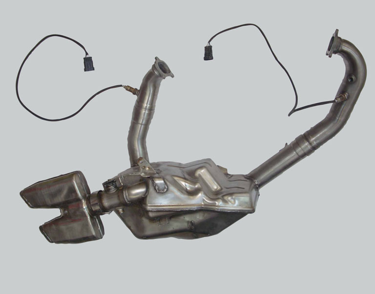
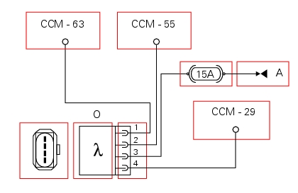
the fuel system no longer functions in a closed loop (the engine control unit disables analysis of the signal received from the oxygen sensor and therefore functions in an open loop)
|
|
-
|
Oxygen sensor for cylinder 1 - horizontal and/or oxygen sensor for cylinder 2 - vertical, open circuit: check integrity of electric circuit and electrical connections.
|
|
-
|
Oxygen sensor for cylinder 1 - horizontal and/or oxygen sensor for cylinder 2 - vertical, short circuit to Vdc: check integrity of electric circuit and electrical connections.
|
|
-
|
Oxygen sensor for cylinder 1 - horizontal and/or oxygen sensor for cylinder 2 - vertical, short circuit to ground: check integrity of electric circuit and electrical connections.
|
|
-
|
Oxygen sensor heater for cylinder 1 - horizontal and/or oxygen sensor heater for cylinder 2 - vertical, short circuit to ground: Check integrity of fuse, electrical circuit and electrical connections.
|
|
-
|
Oxygen sensor heater for cylinder 1 - horizontal and/or oxygen sensor heater for cylinder 2 - vertical, open circuit: Check integrity of fuse, electrical circuit and electrical connections.
|
|
-
|
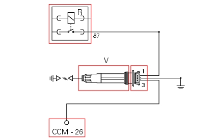
If power supply voltage (12 V – KEY ON) is present on PIN 3 of the lambda sensor (if not, consult Sect. 6 - 7 “The Hands Free system).
|
|
-
|
|
-
|
|
-
|