|
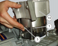
1
|
|
12
|
|
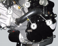
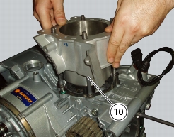
Remove the timing belt covers and the timing belts
|
|


|
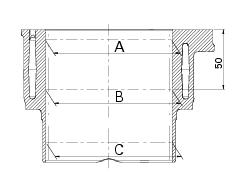
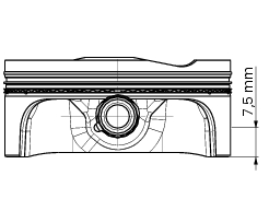
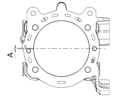
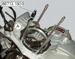
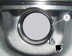
Distance (A) mm
|
||


|
Refit the timing belt external covers and the timing belts
|
|