|
12
|
|
14
|
|
17
|
|
20
|
|
22
|
|
23
|
|
Remove the timing belt covers and the timing belts
|
|

|
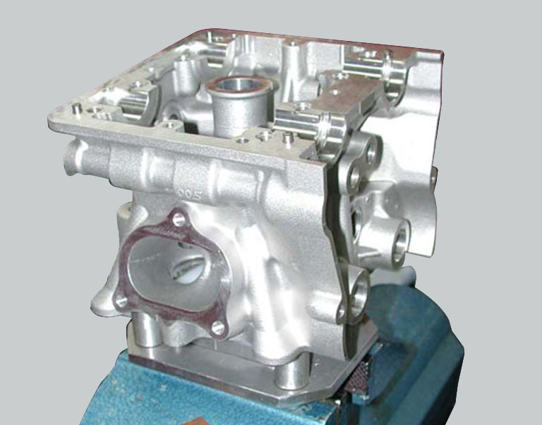
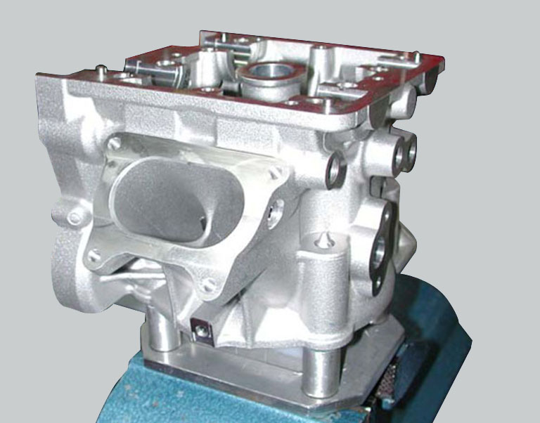
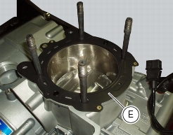
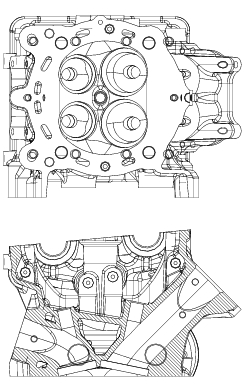
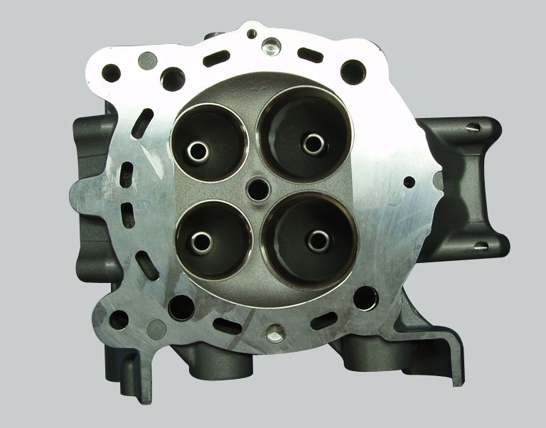
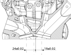
Remove the cylinder head assembly from the engine
|
|
|
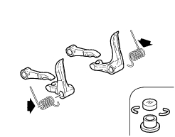
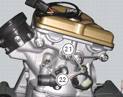
Remove the cylinder head covers, the timing shaft supports and the timing shafts
|
|
-
|
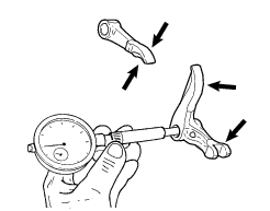
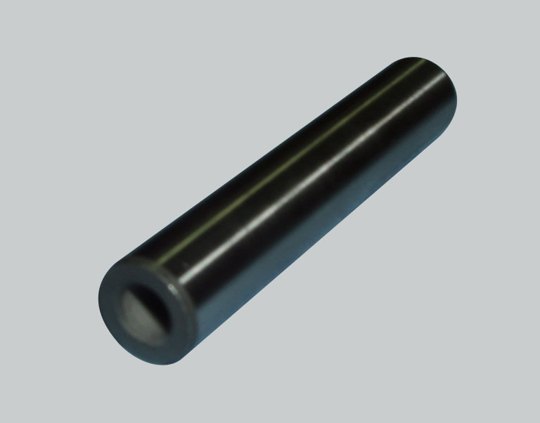
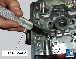
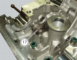
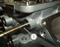
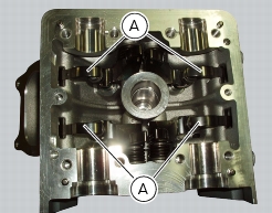
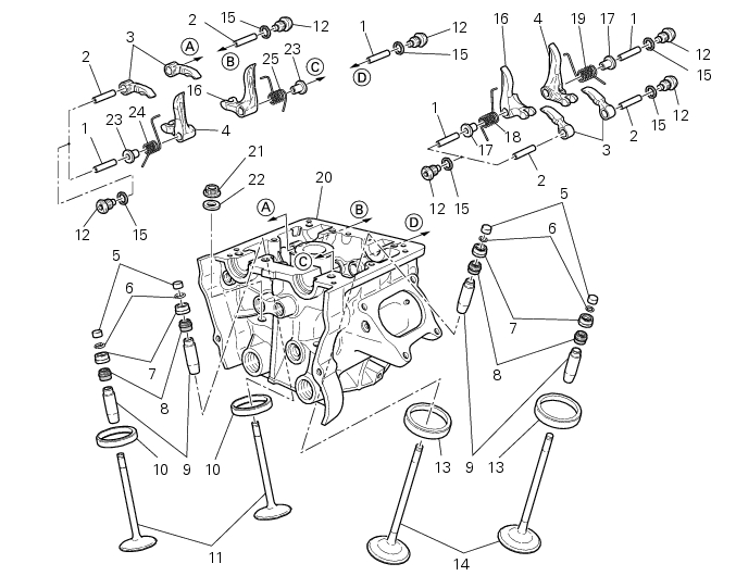
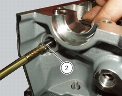
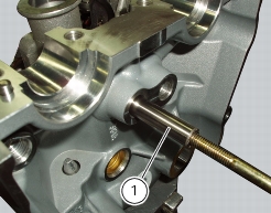
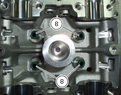
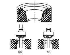
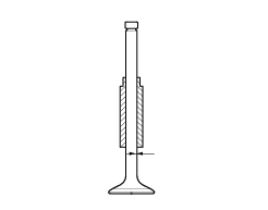
remove the original valve guides using tool no. 88713.2842;
|
|
-
|
|
-
|
|
-
|
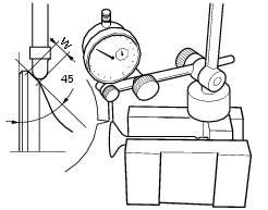
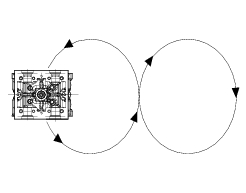
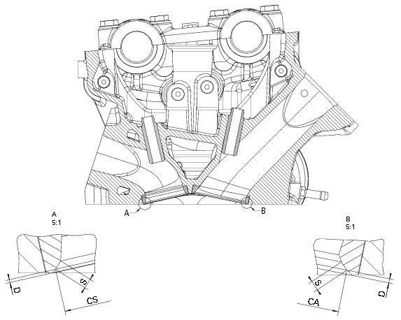
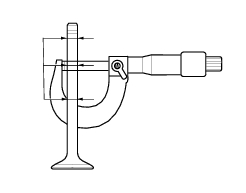
nominal concentricity: 0.01 mm;
|
|
-
|
service limit: 0.03 mm.
|