11 -
Using a multimeter to check the electrical systems
Introduction
This instrument allows you to measure resistance, voltages, and current values. Multimeters can be divided into two basic types: analogue and digital display multimeter. An analogue multimeter has a pointer display. The dial is marked with the scales to be used for measurement of the various parameters. Digital units are equipped with a dial that displays numbers corresponding to the values of the measured parameters. The type of measurement to be carried out (voltage, current or resistance) is set by means of a selector or by means of several different sockets in which to insert the two test probe connector terminals. In certain cases it is essential to set the full scale value before proceeding. For example, inorder to measure a 12 V signal, you need to set a full scale that is close to this value (e.g. 15 V or 20 V). It would be illogical to set a full scale value of 10 V; the same applies when setting current (Amperes) or resistance (Ohms). Sometimes the instrument can set the required full scale value automatically. Never exceed the maximum value allowed by the tester when measuring voltage or current signals.
Note
The DDS diagnosis instrument (Sect. 6 -11, DDS diagnosis instrument) can fulfil the function of digital multimeter.
Voltage measurement
Voltage measurements must be carried out by connecting the terminals of the tester in parallel to the load (e.g. to the wires feeding a light bulb or a relay, the two battery terminals, or the two wires supplying power to a control unit). Voltages can be constant over time (DC voltage) or variable over time (AC voltage). In the first case, it is important to consider the negative and positive polarity of the application. It is therefore necessary to select on the multimeter the type of voltage you intend to measure. (DC voltage is shown by the symbol = while AC voltage is denoted by ~).
Current measurement
Current measurements must be made by connecting the multimeter terminals in series with the load (e.g. disconnect one of the wires feeding power to a light bulb and connect one terminal of the multimeter to the free end of wire and the other terminal to the light bulb. When the lights switch is set to ON, the bulb will illuminate normally and the tester will show the absorbed current, i.e. the amount of current passing through the wire. Important: connections in series must be made and removed only when the power is switched off. Never attempt to make or break a series connection when a device is powered. Always make sure that the connection in series of the tester terminals on the electrical device is made is a safe manner in such a way that it cannot be broken accidentally.
Measurement of resistance values and electrical continuity
Resistance measurements must be taken only when the electrical device or section of the circuit is not powered and isolated from the main electric system (i.e. not connected to the main electric system). These measurements can be utilised to check the resistance value across several sensors. For example, after disconnecting the electrical wiring to the rpm/ignition-injection sys­tem timing sensor (on the camshaft drive gear) the relative internal resistance can be checked by connecting a multimeter to its terminals. This makes it possible to check the electrical continuity of the winding inside the sensor (a reading of infinite resistance indicates that the winding is interrupted). Resistance measurement can also be used to check the continuity of sections of the electrical circuit or relay type switches. For example, to check the condition of a section of the electrical circuit between two connections, disconnect the connections and connect the terminals of the multimeter to the ends of the electrical cable in ques­tion to check that the specified resistance value is present. If this value is close to zero (i.e. lower than approximately 0.3 ohm) this means that the cable is not interrupted. Some instruments feature an audible signal that is emitted when the resistance ap­proaches a value of zero. The same procedure must be adopted to check whether, for example, two contacts of a switch (relay or manual type) are making the contact correctly when closed. In this case the terminals of the multimeter must be connected to the switch terminals, checking that the resistance value is close to zero (or listening for the audible signal) when the switch is closed. To check that the multimeter is functioning correctly in “electrical continuity test” mode, short out the two test probes. The resistance value indicated must be almost nil and the audible signal must be activated.
Protections and precautions
The multimeter is equipped with protective fuses and batteries. These components must always be in perfect condition to ensure that the instrument is functioning correctly. When making electrical measurements always use the maximum caution to avoid short circuits, which can otherwise cause irreparable damage to the electric system and constitute a personal injury hazard. All maintenance work must be performed exclusively when the system is not live (disconnect the battery in advance). NEVER connect the multimeter in parallel to make current measurements, and NEVER connect it in series to carry out voltage measurements.
 
Description of the diagnosis instrument (DDS)
The “DDS” diagnostic system lets you diagnose any faults in the injection-ignition system via a serial port. The system is also equipped with functions to test various devices on the motorcycle. The DDS diagnosis instrument can be used to measure cur­rent and voltage on any electrical device, to perform tests on individual components and to measure pressure and temperature values.
The DDS diagnosis instrument (1) part number 97900.0215 consists of a palmtop display (A), a BBAD self-diagnosis module (B) and a display memory card (C).
The touch-screen display unit (A) serves for both data display and input, using the stylus housed on the side of the unit.
The self-diagnosis module (B) enables communication between the DDS diagnosis instrument (1) and the motorcycle’s on-board electronic control unit (ECU).
The user interface software resides in the display memory card (C) which is housed in the Palmtop display unit (A).
The display unit is equipped with two connection panels: one at the top of the instrument and one at the bottom.
The top connection panel has 6 connection sockets with the following functions:
-
-
-
-
-
The bottom connection panel has 3 connection sockets with the following functions:
-
-
-
You can connect a printer to the DDS diagnosis instrument (1) to print test reports: connect the printer to the serial port (COM1) (G) located on the top connection panel of the tester (1).
Technical data
Power supply:
-
-
Components supplied with the DDS diagnosis instrument
The DDS diagnosis instrument (1) is supplied in a kit together with the following items:
-
-
-
-
-
-
-
-
Tester power supply
The DDS (1) part number 97900.0215 can be powered from the vehicle as follows:
-
-
-
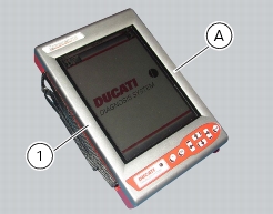
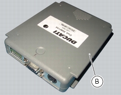
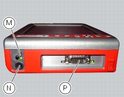
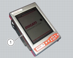
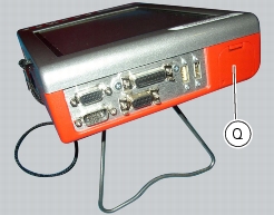
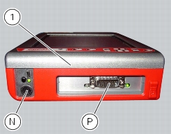
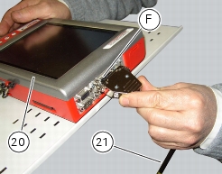
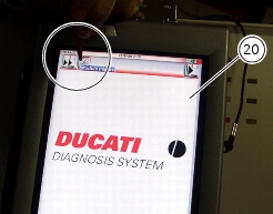
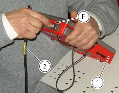
from the tester's internal battery: the battery (Q) is housed in the top part of the tester. To operate the tester (1) using the internal battery and to recharge the battery, refer to the “User Manual” supplied with the DDS diagnosis instrument.
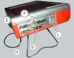
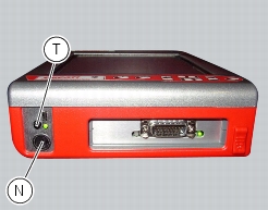
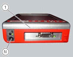
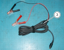
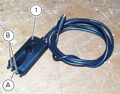
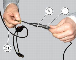
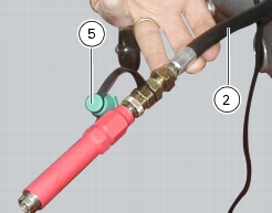
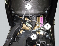
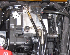
To switch on the display, press the button (T).
Connection to the motorcycle
The tester requires a power supply voltage within 9 and 16 Volts D.C.
Make sure voltage never drops below this limit during operation: this situation could occur during engine starting and idling on motorcycles in which the battery is not in perfect working order. If the tester detects a power supply voltage lower than 9 Volts, the current procedures will be reset; when the voltage returns to the acceptable tolerance limits the procedure must start again from the beginning.
The DDS diagnosis instrument (1) may be powered from the motorcycle in any one of the following ways:
-
-
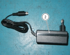
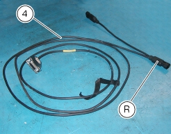
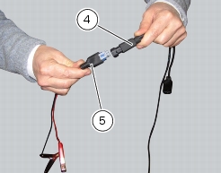
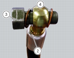
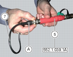
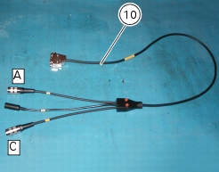
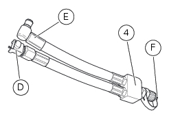
by connecting the instrument diagnosis connector (P) with the power supply and diagnosis cable (4) part no. 97900.0227S; then connect the supply and diagnosis cable outlet (R) with the battery adaptor (5) part no. 97900.0228 and the adapter to the bike battery.
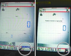
Note
For connection of the various devices required for self-diagnostic procedures, consult the instruction handbook supplied with the tester.
DDS diagnosis instrument
The main functions of the DDS diagnosis instrument can be summarised as follows:
-
-
-
Active diagnostics. Activation of ignition-injection system transducers to test functionality and control signals (fuel pump, igni­tion coils, rev counter, injectors, etc.). With this function it is also possible to enter the code to override the immobilizer.
-
Road test. Allows the technician to store engine parameters recorded within a previously specified engine speed range interval. The resulting parameters can then be analysed and displayed once they have been acquired.
-
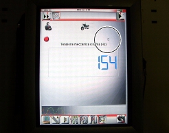
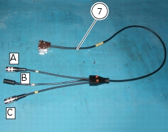
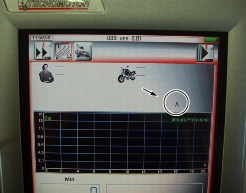
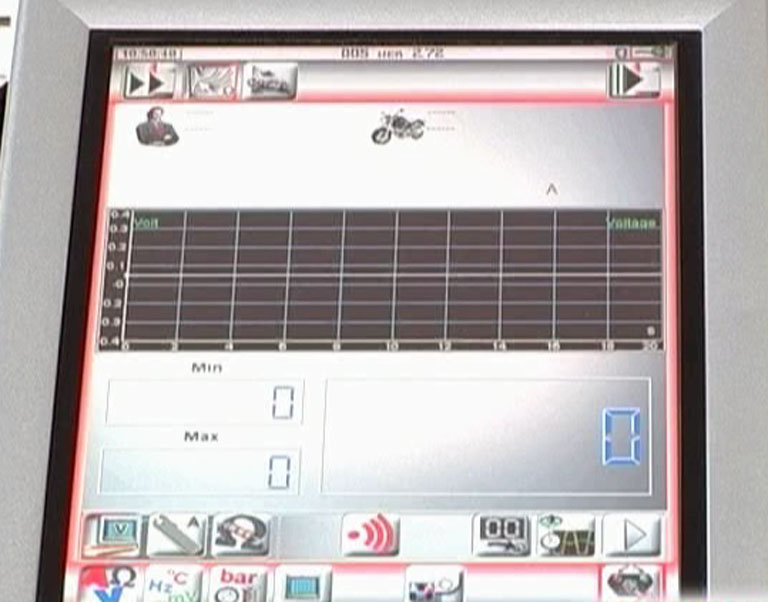
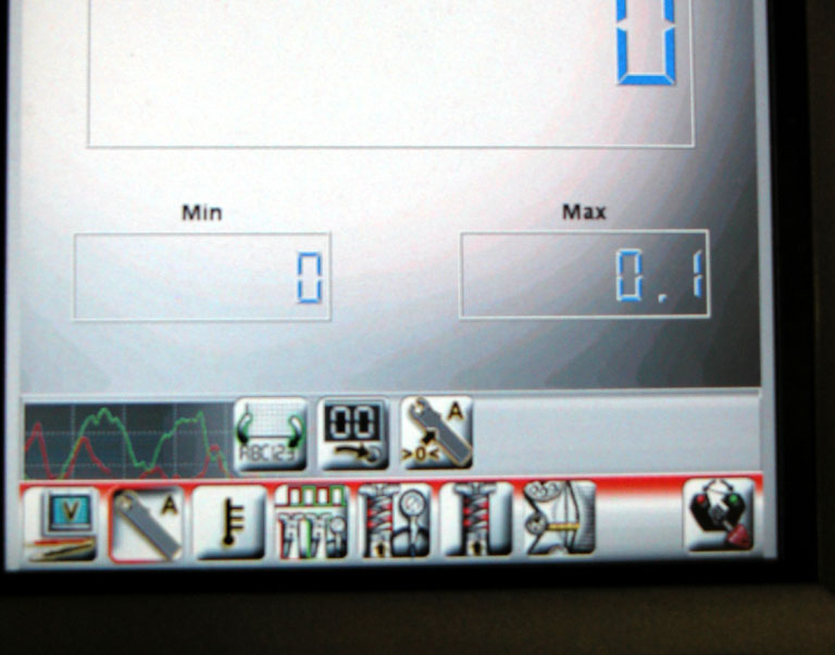
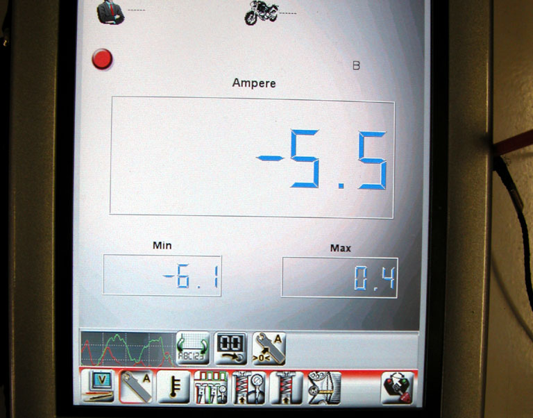
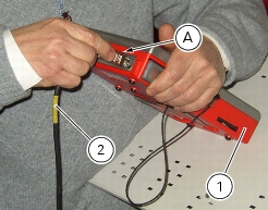
With specific sensors connected, the DDS diagnosis instrument can read electrical voltages, current, temperature, timing belt tension, and pressure values (lubrication and fuel supply circuits for example).
Checking and adjusting timing belt tension
Note
The on-screen icons used during this procedure are explained in a table at the end of this section.
Note
This operation, which is performed using the DDS diagnosis instrument, has the advantage that it can be carried out on both timing belts with the engine still installed on the frame. The DDS shall be connected with an optical reader (1) part no. 88765.1371. The optical reader has a green LED that serves to determine that the reader is correctly positioned in front of the belt to be tested. It is also equipped with an infrared transmitter (A) and receiver (B) designed to detect oscillations of the belt when caused to vibrate with the flick of a finger.
 
 
Remove the cover (2) undoing the screws (3).
Remove the fastening clamps (4) of the ABS tubes (5) and release them from the frame fasteners (6).
Disconnect the connectors (7) of the stepper motor (8) and of the vertical cylinder absolute pressure sensor from the airbox.
Undo the retaining screw (9) of the intake duct (10) and remove it.
 
Loosen the clamp (11) that retains the pipe (12) with the blow-by valve.
Undo the screws (13) that retain the oil breather tank (14) and remove it.
Loosen the clamps (15) and position the airbox on the vehicle without removing the cables of the throttle twistgrip.
Position the crankshaft so that the piston of the horizontal cylinder is at TDC of its power stroke.
This is achieved by aligning the timing mark (C) of the timing driveshaft pulley (16) with the reference notch (D) on the clutch cover (17).
Measure the horizontal timing belt on the section (18) as described in paragraph “Measuring the timing belt tension values”.
Turn the crankshaft by 270° in the engine rotation direction (vertical cylinder TDC, in the combustion stroke) and repeat the pro­cedure used for the horizontal cylinder, measuring the voltage on branch (19) of the vertical belt.
Remove the belt tension sensor and disconnect the DDS diagnosis instrument from the motorcycle.
 
Refit the airbox tightening the clamps (15) to a torque of 2.5 ± 10% (Sect. 3 - 3, Frame torque settings).
Refit the oil breather tank (14) by starting and tightening the screws (13) to a torque of 5 Nm ± 10% (Sect. 3 - 3, Frame torque settings).
Refit the pipe (12) of the blow-by valve fastening the clamp (11) to a torque of 1.5 ± 10% (Sect. 3 - 3, Frame torque settings).
Refit the intake duct (10) by tightening the screws (9) to a torque of 5 Nm ± 10% (Sect. 3 - 3, Frame torque settings).
Connect the connectors (7) of the stepper motor and (8) of the vertical cylinder absolute pressure sensor.
Block the ABS pipes (5) to the fasteners (6) of the frame, replacing the clamps (4).
Refit cover (3) by tightening the screws (2) to a torque of 3.5 Nm ± 10% (Sect. 3 - 3, Frame torque settings).
 
Measuring the timing belt tension values
Switch on the DDS (20) part no. 97900.0215 referring to paragraph “Tester power supply”.
Connect the power and diagnosis cable (Measurement Module) (21) part no.97900.0222 to measurement module connector (F) of the DDS (20).
Connect the belt tension sensor (1) part no. 88765.1371 to the outlet (V) of the supply and diagnosis cable (Measurement Module) (21) part no. 97900.0222.
Fix the mounting bracket of the belt tension sensor (1) using the chain guard retaining screw (22).
Direct the central green LED of the sensor (1) at the midpoint of the belt section, placing sensor (1) parallel to the belt and at a distance of about 1÷1.5 cm from it.
On the DDS diagnosis instrument (20), select the “Measurement module” function by pressing the corresponding icon; then press the “Belt Tension” icon followed by the “Start” icon to access the “Mechanical belt tension” screen.
The socket to which the cable (Measurement Module) (21) is to be connected is indicated on the screen with a capital letter: A, B or C.
Flick the belt lightly with your finger and read the frequency value (Hz) on the DDS diagnosis instrument.
Note
Do not stress the belt several times repeatedly, since the necessary minimum time for the DDS diagnosis instrument to take a reading is 1 second.
 
The tension values are those detailed in Sect. 3 - 1.1, Timing system/valves and must be checked when the engine is cold: as­sembly values must be applied with when installing a new belt, while service values must be applied when belt tension reaches 70 Hz.
Warning
The timing belts can become slack during normal operation. When checking belt tension, if the reading is less than 70 Hz, reten­sion the belt to restore the specified nominal values (Sect. 3 - 1.1, Timing system/valves).
 
If the tension value is incorrect, increase or reduce belt tension, moving the adjustable tensioner pulley (23), loosening the nut (24): to tension the belt use the tool with part no. 88713.3497.
Tighten the nut (24) securing the tensioner pulley.
Recheck the timing belt tension.
Repeat the above procedure until the correct belt tension is obtained.
Once the belts are correctly tensioned, ensure that the fixing nut (24) of the tensioner pulley (23) is tightened to a torque of 25 Nm (Min. 22 Nm - Max. 28 Nm) (Sect. 3 - 3, Engine torque settings).
Checking the idle speed
Check that the bike is provided with electronic control unit, OEM intake and exhaust systems, otherwise fit original components.
Connect the inserts of the exhaust gas analyser part no. 88713.1010 to the outlets of the exhaust pipes using the fittings of the tool.
Warning
On the versions provided with DES, on the vertical cylinder the insert could touch the shock absorber pre-load pipe (A), thus have care to thermically insulate the two components (pipe and insert) to avoid any damage.
Make sure that the throttle body pulley is completely against the anti-stitching screw.
Make sure that the throttle cable free play is correctly adjusted.
 
Check the idle and the CO amount at idle and with warm engine:
1
2
3
4
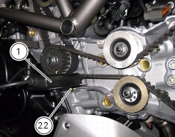
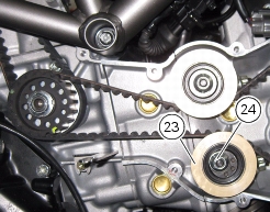
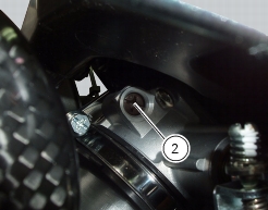
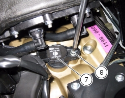
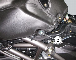
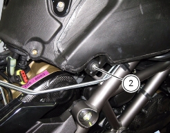
check that the system automatically maintains the idle between 1300 and 1400 rpm (in case the idle is too high check for no cracks or cuts in the intake manifolds, and that the latters are well tightened to the engine, check for no cuts in the pressure sensor pipes, and so on; in case the idle is too low, open by 1/4th of a turn at a time the by-pass (2) of both cylinders con­temporarily);
5
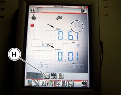
wait that the engine temperature reaches 50°- 60° C displayed on the DDS: apart from the air temperature detected by the DDS, the CO in this engine temperature range must be higher by 1.5% on both cylinders; if this check is not successful, inspect the faulty cylinder (clearance, strokes, valve seal, etc.);
6
wait that the engine temperature exceeds 85°C displayed on the DDS: if the air temperature detected by the DDS ranges between 19 °C and 35 °C the CO in these engine temperature conditions must be within 0.4% and l'1.4% on both cylinders; if this check is not successful try to replace the lambda sensor of the faulty cylinder and, in case the problem still occurs, inspect the faulty cylinder (clearance, strokes, valve sealing, etc.).
Warning
If the engine is shut off during the CO level check, wait three minutes after starting for the after-starting enrichment phase to be finished and the lambda sensors to start operating.
 
Check the engine oil pressure
Note
The on-screen icons used during this procedure are explained in a table at the end of this section.
 
To measure the pressure of the lubrication circuit, use the engine oil pressure test point (19) as described below.
 
Disconnect the wiring connector (F) of pressure switch (1) and remove it taking care to recover the seal.
Insert in the pipe union fitting (2) part no. 875.1.065.1A the fitting (3) part no. 814.1.114.1A, by putting the two copper gaskets (4). Fit in the threaded hole the fitting (3) of pipe (2), by tightening it fully home. Refit on fitting (3) the pressure switch (1), with the relevant gasket and reconnect it to connector (F) of the electric system.
Connect the pressure sensor (5), part no. 552.1.039.1A, to the hose (2), in order to convert the pressure reading into an electric signal.
Turn on the DDS diagnosis instrument (6) referring to the paragraph “Tester power supply”.
Connect the power and diagnosis cable (Measurement Module) (7) part no. 97900.0222 to the measurement module connector (B) of the DDS (6).
Connect the pressure sensor (5) to socket (A) or (C) of the cable (7).
On the DDS diagnosis instrument (1), select the “Measurement module” function by pressing the corresponding icon; then press the “Pressure Test” icon (D) followed by the “Start” icon (E).
The socket to which the cable (Measurement Module) (7) is to be connected is indicated on the screen with a capital letter: A, B or C.
Start the engine.
The values may be displayed in three different ways: in one numeric form and in two graphic forms; to select the desired display type, press the “Value display” icon.
The measured value is indicated alongside the letter (A) or (C) identifying the cable used for the measurement: i.e. if you used connector (A) of the cable (3), the value measured will displayed next to the letter (A) on the screen.
Oil pressure test values:
Warm engine
(Minimum oil temperature = 80 °C)
1100÷1300 min1
greater than 0.8 bar.
3500÷4000 min1
greater than 4 bar.
Important
The maximum pressure must never exceed 6.0 bar.
 
Excessively high pressure may indicate that the relief valve is stuck. Excessively low pressure, on the other hand, may be caused by the relief valve being stuck in the open position, the relief valve spring being too weak, or a faulty oil pump. Other causes are excessively worn seals and gaskets or a badly worn engine.
 
Remove the gauges and refit the pressure switch (1) with its seal. Tighten it to a torque of 19 Nm ± 10% (Sect. 3 - 3, Frame torque settings).
Connect the electrical system connector (F) to the pressure switch.
Disconnect the DDS diagnosis instrument.
 
Cylinder compression test
Note
The on-screen icons used during this procedure are explained in a table at the end of this section.
 
Engine performance is directly correlated to the pressure that can be measured in the combustion chambers of the two cylinders. Pressure which is too high/low or an excessive difference between the two cylinders will cause a drop in engine performance and can cause engine breakdowns.
 
 
To access the vertical cylinder head spark plug raise the tank by undoing the screws (1) and (2) and installing a mounting under it.
Disconnect the fuel sensor connector (3), the fuel pump connector (4) and the snap fittings (5) of the flange.
In order to access the horizontal spark plugs big end unscrew the water radiator fixing screws (6) slightly moving it upwards.
Run the engine so that it warms up to the point that the fan is tripped at least once.
Open the throttles completely.
Remove the HT leads (7), unscrewing the nuts (8) of both spark plugs.
Remove the spark plug from the cylinder to be tested.
Connect the HT lead to earth to prevent sparking.
Screw the cylinder compression cable part no.552.1.038.1A into the spark plug compartment.
Connect the pressure sensor part no. 552.1.039.1A to the cable with part no. 552.1.038.1A.
Turn on the DDS diagnosis instrument (9) referring to the paragraph “Connection to the motorcycle”.
Connect the power and diagnosis cable (Measurement Module) (10) part no. 97900.0222 to the measurement module connector (B) of the DDS (9).
Connect the pressure sensor part no. 552.1.039.1A to the outlet (A) or (C) of cable (10) part no. 97900.0222.
Note
Measure the compression on one cylinder at a time.
On the DDS diagnosis instrument (9), select the “Measurement module” function by pressing the corresponding icon; then press the “Cylinder Compression” icon (D) followed by the “Start” icon (E).
The socket to which the cable (Measurement Module) (10) is to be connected is indicated on the screen with a capital letter: A, B or C.
Turn over the engine with the starter motor until the pressure stops rising.
Check the pressure in each cylinder:
-
standard value: 11 to 12 bar;
-
-
An excessively high pressure value can be caused by:
-
An excessively low pressure value can be caused by:
-
-
-
-
-
 
Refit the spark plugs and position the HT leads (7) in the corresponding compartments and tighten the nuts (8) to a torque of 10 Nm (Min. 9 Nm Max. 11 Nm) (Sect. 3 - 3, Frame torque settings).
Fix the radiator to the support by starting and tightening the screws (6) to a torque of 10 Nm±10% (Sect. 3 - 3, Frame torque settings).
Connect the fuel sensor connector (3), the fuel pump connector (4) and the snap fittings (5) of the flange.
Refit the fuel tank by tightening the screws (1) and (2) to the specified torque of 10 Nm ±10% (Sect. 3 - 3, Frame torque settings).
 
 
Fuel pressure test
Note
The on-screen icons used during this procedure are explained in a table at the end of this section.
 
 
Slightly lift the tank by undoing the screws (1) and (2) and fit a mounting under it so that it can be operated on the flange couplings.
Remove one of the two pipes of the fuel system (3).
Use the fuel pressure pipe (4) part no. 590.1.189.1A by connecting one end (D) to the coupling of the delivery pipe to the tank and the other end (E) to the fuel system pipe (3): in this way you create a pressure pick-up socket (F).
Connect the pressure sensor (6) part no. 552.1.039.1A, to the outlet (F) of hose (4), in order to convert the pressure reading into an electric signal.
Turn on the DDS diagnosis instrument (7) referring to the paragraph “Tester power supply”.
Connect the power and diagnosis cable (Measurement Module) (8) part no. 97900.0222 to the measurement module connector (E) of the DDS (1).
Connect the pressure sensor (6) part no. 552.1.039.1A to outlet (A) or (C) of the cable (8).
On the DDS diagnosis instrument (7), select the “Measurement module” function by pressing the corresponding icon; then press the “Pressure Test” icon (F) followed by the “Start” icon (G).
The socket to which the cable (Measurement Module) (8) is to be connected is indicated on the screen with a capital letter: A, B or C.
The values may be displayed in three different ways: in one numeric form and in two graphic forms; to select the desired display type, press the “Value display” icon (H).
The measured value is indicated alongside the letter (A) or (C) identifying the cable used for the measurement: i.e. if you used connector (A) of the cable (8), the value measured will displayed next to the letter (A) on the screen.
The maximum pressure must be equal 3 bar (nominal).
Once the test is over, remove all the components of the test instrument and refit the fuel system pipe (3).
Refit the fuel tank by tightening the screws (1) and (2) to the specified torque of 10 Nm ± 10% (Sect. 3 - 3, Frame torque settings).
 
Guided diagnosis
Note
The on-screen icons used during this procedure are explained in a table at the end of this section.
 
The DDS diagnosis instrument guides the operator step-by-step through the various diagnostic procedures, providing descriptions and documentation for motorcycle components, wiring diagrams for the electronic systems and informa­tion on the locations of specific components.
 
Turn on the DDS diagnosis instrument (1) referring to the paragraph “Tester power supply”.
Connect the power and diagnosis cable (2) part no. 97900.0227 to the diagnosis connector (F) to the diagnosis socket (3) of the motorcycle.
Enter the general functions menu by pressing the icon “Menu 1” (A).
Press the “Select vehicle” icon and, on the next screen, press the “Select motorcycle” icon; select the motorcycle model and confirm, then select the version and confirm.
Press the icon “Select system” to display a list of the bike’s systems that can be analysed.
Select one of the options shown in the following picture and press icon “Confirm“ (B) to confirm it.
Press the “Guided diagnosis” icon (C) to access the corresponding function.
A series of screens are displayed indicating the operations required for correct diagnosis.
To determine whether the system has any internal problems, you can access the “Self-diagnosis” function by pressing the cor­responding icon. If any errors are present, the symbol (D) will be displayed. To determine the type of errors present, press the “Errors” icon (E). Once errors are detected, it is possible to solve them using the Step-by-step diagnosis; press “Step-by-step diagnosis“ icon (C).
The DDS diagnosis instrument will interrogate the electronic control unit and display the parameters analysed with their relative values.
 
Testing the battery charging system
Note
The on-screen icons used during this procedure are explained in a table at the end of this section.
 
You can determine the engine rpm required for generator to produce just enough current to charge battery, feed the injection ignition system and all electric items fitted to motorcycle. When applied to a cable, the clamp-type amperemeter (1) part no. 88765.1126V detects the magnetic field generated by the current passing through that cable.
 
Turn on the DDS diagnosis instrument (2) referring to the paragraph “Tester power supply”.
Connect the power and diagnosis cable (Measurement Module) (3) part no. 97900.0222 to the measurement module connector (D) of the DDS (2).
Connect the clamp-type amperemeter (1) to the connector (E) of the power and diagnosis cable (Measurement Module) (3).
Warning
The clamp-type amperemeter must not be connected to wires through which electrical current is flowing.
 
Insert the clamp-type amperemeter into the battery positive terminal lead with the arrow on the clamp pointing towards the bat­tery positive terminal (+).
On the DDS diagnosis instrument (2), select the “Measurement module” function by pressing the corresponding icon; then press the “Ammeter” icon (F) followed by the “Start” icon.
The socket to which the cable (Measurement Module) (3) is to be connected is indicated on the screen with a capital letter: A, B or C.
If the measured current is a positive quantity, it means that generator is feeding all electric items and charging battery at the same time. If the current has a negative sign, this means that the charging system is not able to power the electrical loads and a sig­nificant amount of the current required must be supplied by the battery, which is therefore discharging.
Important
If polarity is reversed when clamping the ammeter onto the cable, the sign of the readings will also be reversed, giving rise to incorrect diagnosis.
 
Deactivating the “service” indication on the instrument panel
The message “SERV” is displayed on the instrument panel, indicating that the motorcycle should be serviced in accordance with the programmed maintenance plan. This indication is activated after the first 1000 km and thereafter at intervals of 12000 km.
 
After the scheduled service has been carried out, the indication must be switched off as follows:
Note
The on-screen icons used during this procedure are explained in a table at the end of this section.
 
Turn on the DDS diagnosis instrument (1) referring to the paragraph “Tester power supply”.
Connect the power and diagnosis cable (2) part no. 97900.0222 to the diagnosis connector (A) and the latter to the diagnosis socket (3) of the motorcycle.
 
Enter the general functions menu, pressing “Menu Key 1“ icon (B).
Press the “Vehicle selection“ icon and press “Vehicle selection“ icon in the following page; select the motorcycle model and confirm, then select the version and confirm.Press the “Select system” icon.
A list of the motorcycle’s systems that can be analysed will appear on the display.
Select the icon “INSTRUMENT PANEL“.
 
Press the “Confirm” icon (C) to confirm it. Next, press the “Self-diagnosis” icon to access the corresponding function.
The DDS diagnosis instrument will interrogate the electronic control unit and display the parameters analysed with their relative values.
Press the “Settings” icon to display the special parameters.
Select “Service light OFF“ and press “Execute“.
On completion of the operation, the message “Was the operation completed successfully?” will appear; press “Confirm” (C).
If any problems were encountered during the operation, the tester will display the relative error messages: you need to confirm or reject each message by pressing “Confirm“ (C) or “Exit“ (D), respectively.
Note
Once the “service“ light has been reset with the DDS diagnosis instrument, set the ignition switch to OFF and wait for at least 30 seconds before switching it ON again.
 
Icons table