2 -
1
2
3
4
5
6
7
8
9
10
11
12
13
14
15
16
17
18
19
20
21
 Spare parts catalogue
Important
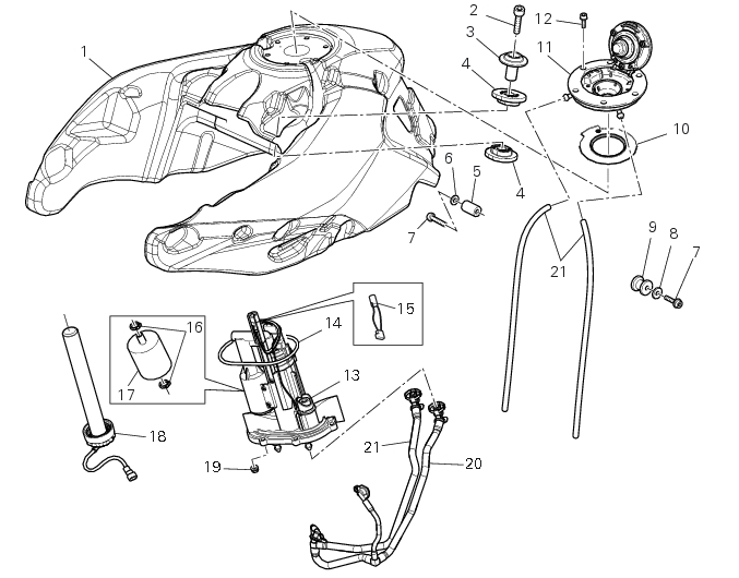
Bold reference numbers in this section identify parts not shown in the figures alongside the text, but which can be found in the exploded view diagram.
Removal of the fuel tank
Working from both sides, loosen and remove the rear fixing screw (7)
Working from both sides, loosen and remove the front fixing screw (2)
Slightly lift the tank to facilitate the following operations.
Disconnect the fuel pump connector (A) and the fuel level sensor connector (B).
Disconnect the two quick release couplings (C) of the fuel pipes.
Remove the clamp (D) to release the wiring of the fuel level sensor (B) from the fuel pump wiring (A).
Operating on both sides of the tank plug, slide off the two fixing clamps (E) and the two breather pipes (21).
On both sides of the tank plug, paying attention not to damage them, slide the two breather pipes (21).
Remove the tank (1).
 
Removing the tank plug and fuel sensor unit
Undo and remove the six fixing screws of the tank plug (12).
Remove the complete plug (11) paying attention to collect the two breather pipes (21).
Recover the seal (10).
Note
In case it proves necessary to replace the lock inside the plug refer to Sect. 4 - 4, Removing the filler plug lock - Sect. 4 - 4, As­sembling the filler plug lock.
Refitting the filler plug unit
Grease the new gasket (10) and the corresponding groove in the fuel tank.
Place the complete plug (11) by paying attention to position the two breather pipes (21) in the relevant seats.
Position and tighten the six fixing screws (12) to the torque of 4 Nm± 10% (Sect.3 - 3, Frame torque settings).
Replacing the tank flange and fuel sensor
Undo the six fixing nuts (19) of the fuel tank flange. Remove three of the bolts, leaving three in position in order to help lift the flange.
Remove the fuel pump (13) from the fuel tank.
Collect the gasket (14).
Undo and remove the two fixing screws (G) and move the protection (F).
Loosen the clamps (16) and slide the fuel filter (17).
Before reassembly, carefully remove any deposits or scale from all parts.
Important
When installing the new filter, position it so that the arrow stamped on the outer casing points towards the flange.
Note
The flange is supplied as a spare part complete with the fuel pump and pressure regulator: the entire flange assembly must be replaced in the event of malfunction.
Remove the sensor (18) securing the tank (1).
 
Refitting the tank flange and fuel sensor
Introduce the flange with the gasket (14) properly greased and refit by reversing the steps of the removal procedure.
Warning
Orientate the fuel pump (13) with the arrows (H) facing the rear part of the tank (1).
 
Apply threadlocker and tighten screws (19) to the torque of 6 Nm ± 10% (Sect. 3 - 3, Frame torque settings).
Important
In the USA version instead of the nuts it is necessary to use screws,
Apply prescribed grease on seal (C) of the fuel sensor (18).
Insert the fuel sensor (18) in tank (1) by orienting it so as to match pins (D) and (E) of the sensors with slots (F) and (G) on the tank inlet (H).
Fix the sensor by starting the ring nut (L) and tighten it to a torque of 8 Nm ± 10% (Sect. 3 - 3, Frame torque settings).
Refitting the fuel tank
Positioning the tank (1).
On both sides of the tank plug, place the two breather pipes (21) and insert them on the plug.
Operating on both sides of the tank plug, position the two fixing clamps (E) of the two breather pipes (21).
Position a clamp (D) to connect the wiring of the fuel sensor (B) to the fuel sensor wiring (A).
Keep slightly raised the tank to facilitate the following operations.
Connect the two quick releasing couplings (C) of the fuel pipes following the removal order, paying attention to insert the delivery on the filler marked with OUT and the return on the filler marked with IN.
Connect the fuel pump connector (A) and the fuel sensor connector (B).
Operating on both sides, position the front fixing screw (2), without tightening it.
Operating on both sides, position the rear fixing screw (7), without tightening it.
Check correct position of the tank and tighten the two front fixing screws (2) and the two rear fixing screws (4) to a torque of 10 Nm± 10% (Sect. 3 - 3, Frame torque settings).
 
Positioning of the fuel tank breather and drain hoses
Positioning of the fuel hoses
 
 
1