10.3 -
1
2
3
4
5
6
7
8
9
10
11
12
 Spare parts catalogue
Important
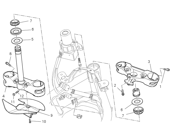
Bold reference numbers in this section identify parts not shown in the figures alongside the text, but which can be found in the exploded view diagram.
Adjusting the steering head bearings
Note
To adjust the steering bearing clearance, follow what is described in Sect. 4 - 3, Adjusting the steering head bearings.
 
If the problems found are not solved, check the wear of steering bearings (7) and replace them, if necessary, as described in paragraph “Removal of the steering head components” of this chapter.
Steering angle adjustment
Loosen the nuts (11).
Loosen the adjusting grub screws (12) on both sides of the bottom yoke.
Use a 6 to 6.5 mm spacer (A) fitted to the fork outer tube, or use a gauge.
Turn the front forks to the right until the spacer (A) is seated against the frame top tube.
Turn the adjuster screw (12) on the opposite side to bring it into contact with the stop on the steering head.
Apply threadlocker to the thread of nut (11).
Hold the dowel (12) firmly and tighten the nut (11).
Turn the forks to the opposite side: and repeat the process to adjust the other screw and tighten the relative lock nut.
Warning
Check the correct operation of the steering lock both on the left and on the right side.
In case of fault repeat the steering programming procedure described above until reaching the bike perfect setup, i.e. when the steering lock works properly. After performing this check, make sure that when the handlebar is fully turned to the left, the clutch master cylinder filler does not interfere with the fuel tank, and when the handlebar is fully steered to the right, the twistgrip does not touch the fuel tank.
 
Removal of the steering head components
Note
All parts fitted to the top and bottom yokes, including the wiring and control cables, can remain on the motorcycle provided they do not hinder the following operations.
 
Loosen the screw (2) fastening the steering head (3) to the ring nut (5).
Remove the steering head (3).
With the tool with code. 88713.1058 loosen the ring nut (5) and unscrew it from the steering pin.
Slide the sealing ring (6), the inner ring (A) and the ball race (B) of the upper bearing (7) off the steering shaft.
Remove the bottom yoke (1) complete with the steering stem from the frame tube.
Remove the ball race (B) of the lower bearing (7).
The inner ring (A) of the lower bearing (7) and the relative sealing ring (6) will remain on the shaft.
Using a universal puller (of the type shown in the figure) remove the ring (A) from the steering stem, taking care not to damage the seat.
Important
Once removed, the sealing rings (6) and the bearings (7) must not be refitted.
 
Using a suitable drift, remove the outer bearing races (C) from the steering head. Proceed with extreme care to avoid damaging the seats.
Refitting the steering head components
Important
The steering tube bearings (7) are identical but in no case may their components be swapped around during reassembly.
 
Clean all contact surfaces and lubricate with the recommended grease.
To fit the external rings (C) of the bearings (7) to the steering head, use the tool with part no. 88713.1062 and proceed as follows:
-
-
-
-
-
-
Fit the sealing ring (6) (with the rim facing upwards) and inner ring (A) of bottom bearing (7) onto the steering shaft (D) after heat­ing it for about 10 minutes to 120 °C.
Insert drift part no. 88713.1072 onto steering shaft. Press inner ring (A) onto seal (6), manually hold pressed for at least 10-15 seconds.
Lubricate the inner bearing race (A) with the recommended grease.
Fit the ball race (B) to the steering stem (D) with the smaller diameter of the cage facing upwards and grease the ball race.
Insert the steering stem in steering head and push it in until it is axially seated.
Fit the bottom yoke assembly to frame.
Grease the ball race (B) and fit it to outer race (C) of the top bearing.
Fit the inner ring (A) of the upper bearing (7) to the steering head, with the larger diameter facing upwards.
Install the dust sealing ring (6) with the flat side facing upwards.
 
Tighten the adjusting ring nut (5) by hand until it seats against the sealing ring (6).
Fit special bush with part no. 88713.1058 to the ring nut (5) and apply the torque wrench to the bush.
Tighten the adjusting ring nut (5) to a torque of 30 Nm ± 5% (Sect. 3 - 3, Frame torque settings).
Fit the steering head (3) on the adjusting ring nut (5), aligning the fork leg bores with the corresponding bores on the bottom yoke. Refit the fork legs.
Grease the screw (2) with the recommended grease.
Tighten the screw (2) on the steering head to the torque of 18 Nm ± 5% (Sect.3 - 3, Frame torque settings).
If previously removed, place the splashguard (9) on the bottom yoke (1) and fix it by starting screws (10) with recommended threadlocker and tightening them to a torque of 3 Nm ± 10 % (Sect. 3 - 3, Frame torque settings).