|
1
|
|
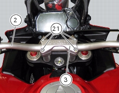
3
|
|
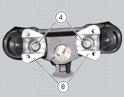
4
|
|
5
|
|
6
|
|
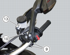
9
|
|
10
|
|
13
|
|
15
|
|
16
|
|
18
|
|
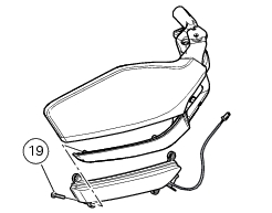
19
|
|
20
|
|
21
|
|
27
|
|
28
|