|
6 -
|
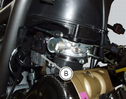
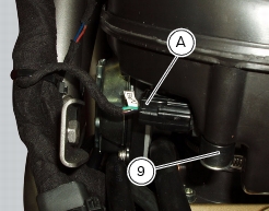
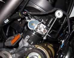
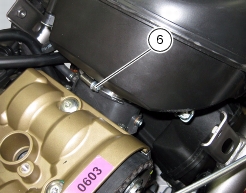
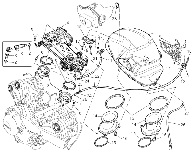
Airbox – Throttle Body
|
|
1
|
|
2
|
|
3
|
|
5
|
|
6
|
|
8
|
|
10
|
|
11
|
|
12
|
|
16
|
|
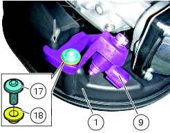
17
|
|
18
|
|
19
|
|
20
|
|
21
|
|
22
|
|
23
|
|
24
|
|
25
|
|
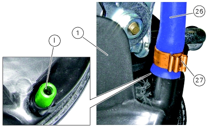
26
|
|
27
|
|
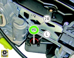
28
|