4.1 -
1
2
3
4
5
 Spare parts catalogue
Important
Bold reference numbers in this section identify parts not shown in the figures alongside the text, but which can be found in the exploded view diagram.
Checking and adjusting the valve clearances
Loosen the water radiator fixing screws and leave the cooling system connected
Note
For clarity, the figures show the engine removed from the frame.
 
Move the piston of the cylinder being checked to TDC of the power stroke: in this condition, all the valves are closed and the timing shafts come in neutral position and, therefore, free to rotate; check to the valve clearance on the cylinder head on which it operates.
Checking the opening clearance
Using a feeler gauge, check the clearance between the opening rocker arm (A) and the lowest point of the camshaft lobe (B), taking care not to compress the rocker arm return spring.
The value must be within the specified ones (Sect. 3 - 1.1, Timing system/valves).
If not, remove the opening adjuster (3), as described in paragraph “Removing the valves” (Sect. 9 - 4.5), and replace it with one of suitable height to obtain the prescribed clearance.
Note
Opening rocker arm shims measuring 1.80 to 3.45 are available as replacement parts: the size is punched on the shim.
Checking the closing clearance
Using a feeler gauge, check the clearance between the closing rocker arm (C) and the highest point of the camshaft lobe (D).
The value must be within the specified ones (Sect. 3 - 1.1, Timing system/valves).
If not, remove the closing adjuster (1), as described in paragraph “Removing the valves” (Sect. 9 - 4.5), and replace it with one of suitable height to obtain the prescribed clearance.
Note
Closing rocker arm shims measuring from 2.2 to 4.5 are available as replacement parts: the size is punched on the shim.
Checking valve lift
Set the engine to the configuration described for the “Checking and adjusting the valve clearances”, previously indicated.
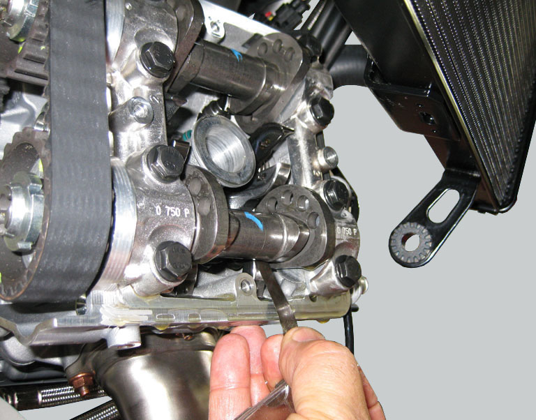
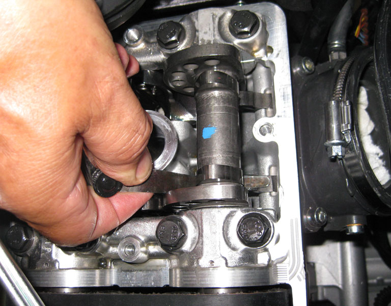
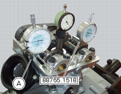
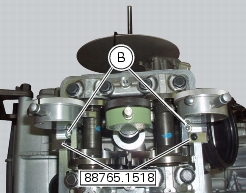
Position the tool 88765.1518 on the cylinder head: the part marked “A” should be on the intake side and the part marked “S” should be on the exhaust side.
Seat the plate (A) and tighten the screws (B).
Set the opening valve clearance to zero when the camshaft is in its rest position by fitting a feeler gauge between the upper rocker arm and the opening shim.
Lock the dial gauge into the seat of the stand marked “A” and position the fork probe against the face of the closing shim.
Set the dial gauge to zero when the valve is fully closed.
Rotate the intake camshaft so as to allow the intake valves to lift fully.
Check on the dial gauge that the measured value corresponds to the prescribed one (Sect. 3 -1.1, Timing system/valves).
Repeat the same operation for the exhaust valves, using the dial gauge in the support seat 88765.1518 with the marking “S”.
Refit the components by carrying out the same operations indicated in chapter “Checking and adjusting the valve clearances”, previously described.
Refit the components removed in the procedure.
Checking the engine timing
Loosen the water radiator fixing screws and leave the cooling system connected
Set the engine to the configuration described for the “Checking and adjusting the valve clearances”, previously indicated.
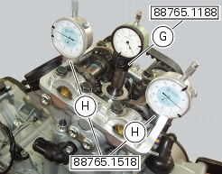
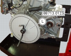
Install tool 88765.1188 (G) in the spark plug bore to determine the piston TDC, the gauges (H) on the tool 88765.1518 and the timing check tool (degree wheel (L) 88713.0123 with graduated disk).
Set the opening valve clearance to zero when the camshaft is in its rest position by fitting a feeler gauge between the upper rocker arm and the opening shim.
Check that in this condition the camshaft can rotate. If it moves stiffly, use a thinner feeler gauge.
In this condition, with the piston of the horizontal cylinder at TDC with the valves fully closed as confirmed by the reading on gauge (G), set the gauges (H) to zero.
Set the tension value of the belts as described at Sect. 6 - 11, Checking and adjusting timing belt tension.
Turn the degree wheel (L) anticlockwise until the gauge dial (H), on the exhaust side, shows a lift of 1 mm. Check that the value of the angular displacement read on the degree wheel (L) is as specified in (Sect. 3 - 1.1, Timing system/valves).
Continue to rotate in the same direction until you obtain a lift of 1 mm on the intake side. Check the angular value on the degree wheel.
Continue to rotate until you obtain an intake valve lift of 1 mm on the gauge (H), during closure of the valve for the compression stroke. Check the angular value with the prescribed one (Sect. 3 - 1.1, Timing system/valves).
Continue to rotate the degree wheel (L) anticlockwise until you obtain a lift of 1 mm of the exhaust valve, when opening or closing the valve.
Check the angular displacement value against the specified value.
Repeat the procedure for the vertical cylinder.
A tolerance of ±3° is allowed in the values detected with the described procedure regarding the prescribed ones (Sect. 3 - 1.1, Timing system/valves).
Remove the installed tools to check timing. Then tension the belts to the value of the prescribed operation, as described at Sect. 6 - 11, Measuring the timing belt tension values.
In case of values different from the described ones (Sect. 3 - 1.1, Timing system/valves), loosen the fixing screws (M) of the timing pulley and correct the value detected by turning the ring nut of the timing shaft with the supplied wrench with code 88713.1806.
Lock the three retaining screws (M) of the timing pulley to the specified torque of 10 Nm (Min. 9 Nm - Max. 11 Nm) (Sect. 3 - 3, Engine torque settings) and mark the new position of the components.
Refit the components removed in the procedure.


1