|
1
|
|
8
|
|
10
|
|
11
|
|
12
|
|
13
|
|
16
|
|
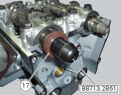
17
|
|
19
|
|
21
|
|
26
|
|
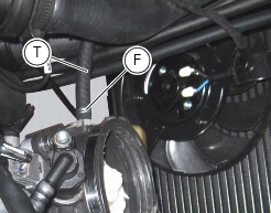
Loosen the water radiator fixing screws and leave the cooling system connected
|
|